
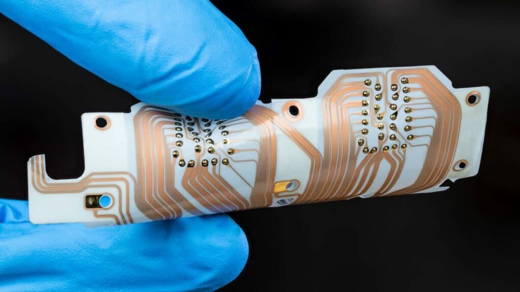

A flexible circuit board, often called a flex PCB, forms the backbone of many modern electronics. This type of pcb bends, twists, and folds to fit into compact spaces where rigid boards cannot go. Manufacturers use flexible materials like polyimide, polyester, or PTFE, which differ from the glass-reinforced FR-4 found in rigid pcbs. The table below highlights these key materials and their properties:
| Material Type | Common Materials | Key Properties |
|---|---|---|
| Flexible PCB Substrates | Polyimide, Polyester, PTFE | High flexibility, thermal stability, chemical resistance |
| Rigid PCB Substrates | FR-4, High-Tg laminates | Mechanical strength, less flexible |
| Conductive Layers | Rolled Annealed Copper | Ductile, ideal for bending |
A flex PCB provides reliable electrical connections while allowing flexibility, making it vital for devices that require both durability and compact design. Flexible printed circuit boards enable engineers to create electronics that are lighter, thinner, and more adaptable than ever before.
Key Takeaways
- Flexible circuit boards bend and fold to fit into small or curved spaces where rigid boards cannot.
- Polyimide is the main material used for flexible PCBs because it resists heat and chemicals while staying strong and flexible.
- There are different types of flexible PCBs, including single-sided, double-sided, multilayer, and rigid-flex, each suited for various device needs.
- Flexible PCBs save space and weight, improve durability, and reduce the number of connectors, making devices smaller and more reliable.
- These boards are widely used in consumer electronics, medical devices, automotive, and aerospace industries due to their flexibility and toughness.
Flexible Circuit Board Basics
What Is a Flexible Circuit Board
A flexible circuit board, also called a flex PCB or flex circuit board, is a type of printed circuit board that can bend, twist, and fold without breaking. Unlike traditional rigid PCBs, flexible circuit boards use thin, bendable materials that allow them to fit into tight or irregular spaces. The industry standard IPC-6013 defines flexible circuit boards by their type, performance class, and installation use. Flex circuit boards can be single-sided, double-sided, or multilayer, depending on the number of conductive layers and complexity.
- Types of Flex Circuit Boards (per IPC-6013):
- Type 1: Single-sided flexible boards with one conductive layer.
- Type 2: Double-sided flexible boards with two conductive layers and plated through holes.
- Type 3: Multilayer flexible boards with three or more conductive layers.
- Type 4: Multilayer rigid and flexible combinations.
- Type 5: Flexible or rigid-flex boards with two or more conductive layers without plated through holes.
Flexible printed circuit boards stand out because they can replace traditional wire harnesses, provide electrical connections in three dimensions, and work in applications that require frequent bending or movement. Flex circuits appear in products like computer keyboards, LCD interfaces, automotive instrument panels, and portable electronics. Their flexibility, thinness, and ability to save space make them essential in modern circuit board design.
Structure and Materials
The structure of a flexible circuit board centers on its unique materials. Manufacturers use flexible polymer substrates such as polyimide or polyester films. Polyimide is the most common choice for flex PCBs because it offers high heat resistance and mechanical durability. This material allows flexible printed circuit boards to withstand soldering processes and harsh environments. Polyester is another option, often used in applications where heat resistance is less critical and cost is a concern.
| Feature | Polyimide Flexible PCB | Polyester Flexible PCB |
|---|---|---|
| Thermal Resistance (Reflow) | Can withstand reflow soldering up to ~300°C | Limited to below ~150°C |
| Working Temperature | Around 200°C | Below 80°C |
| Mechanical Durability | High mechanical strength and flexibility | Limited bending capability; prone to break |
| Electrical Insulation | Excellent dielectric properties | Adequate but inferior to polyimide |
| Chemical Resistance | Resistant to many chemicals | Less resistant |
| Applications | High-performance, high-temperature, harsh environments (automotive, aerospace, industrial) | Low-cost, low-temperature, transparent applications |
Flexible printed circuit boards use copper foil conductors bonded with adhesives to the flexible substrate. This construction allows flex PCBs to maintain electrical performance and structural integrity even when bent or twisted. Polyimide-based flexible circuits perform well under repeated bending, thermal cycling, and exposure to chemicals, making them reliable for critical uses in medical, aerospace, and automotive electronics.
Flexibility vs. Rigid Boards
Flex circuit boards differ from rigid PCBs in both construction and application. Rigid boards use glass-reinforced epoxy laminates like FR-4, which provide mechanical strength but do not allow bending. Flexible circuits, on the other hand, use thin polymer films that enable movement and folding.
Tip: Flexible printed circuits can fit into spaces and shapes that rigid boards cannot, making them ideal for compact and lightweight devices.
The main differences between flexible and rigid PCBs include:
- Construction: Flexible circuits use polyimide or polyester films, while rigid boards use glass-epoxy laminates.
- Mechanical Properties: Flex PCBs can bend, twist, and fold, while rigid boards remain flat and inflexible.
- Applications: Flexible printed circuit boards are preferred in areas where space, weight, and movement matter most. For example, medical devices and implants use flex circuits for their ability to conform to body shapes and withstand vibration. Automotive and aerospace industries rely on flexible circuits for their resistance to extreme temperatures and ability to fit unusual shapes. Mobile consumer electronics use flex PCBs to achieve miniaturization and high circuit density.
| Application Area | Reasons Flexible PCBs are Preferred |
|---|---|
| Medical Devices & Implants | Fit in limited space and weight, durability, shock and vibration resistance |
| Sensors | Ability to withstand harsh environments, chemical and radiation resistance |
| Mobile Consumer Electronics | Miniaturization, three-dimensional packaging, thin and lightweight design |
| Industrial & Manufacturing | High temperature resistance, chemical resistance, durability |
| Aerospace | Resistance to extreme temperatures and vibrations, ability to fit unusual shapes |
| Automotive | Space constraints, thermal performance, integration of multiple sensors and electronics |
| Commercial Electronics | Flexibility for compact, lightweight, and complex device designs |
Flexible circuits offer several advantages over rigid boards, such as reduced size and weight, improved reliability by minimizing connection points, and suitability for harsh environments. However, cost and manufacturing complexity sometimes lead engineers to combine flexible and rigid boards in hybrid designs, known as rigid-flex PCBs, to balance performance and expense.
How Flexible Printed Circuit Boards Work

Electrical Function
Flexible circuits deliver reliable electrical connectivity in environments where space is limited or movement is constant. Engineers design these circuits on flexible substrates such as polyimide films, which allow the circuits to bend, fold, and twist while maintaining electrical integrity. This flexibility enables flexible circuits to fit into tight or irregular spaces, making them ideal for compact devices like wearables, automotive sensors, and medical equipment.
- Flexible circuits withstand repeated motion and vibration, reducing connection failures that often occur in cable-based designs.
- The manufacturing process includes steps such as substrate preparation, image transfer, etching, microvia drilling, and coverlay lamination. Each step preserves both flexibility and electrical reliability.
- Polyimide substrates provide thermal stability, mechanical strength, and chemical resistance, supporting use in harsh or dynamic environments.
- Flexible circuits eliminate bulky connectors and cables, which reduces device size, weight, and potential failure points.
- The ability to tolerate continuous flexing allows for designs with moving parts or foldable sections, without risking cracked traces or solder joints.
Electrical performance in flexible circuits depends on careful design. Controlled impedance is essential for high-speed signals. Designers often use thicker core materials, such as 2–4 mils, to achieve standard impedance values like 60-ohm single-ended or 120-ohm differential signals. Trace geometry and the dielectric constant of the substrate influence impedance and signal integrity. Surface microstrip configurations are common for simple impedance needs, while stripline configurations offer better electromagnetic interference (EMI) shielding but increase board thickness.
Tip: For high-speed flexible circuits, engineers should match differential pair trace lengths and use unbroken ground planes beneath signal traces to maintain signal integrity.
Advanced design strategies, such as stack-up optimization and impedance calculation tools, help ensure that flexible circuits meet electrical performance requirements even in complex, multilayer designs.
Mechanical Performance
Mechanical flexibility sets flexible circuits apart from traditional rigid boards. These circuits can bend, fold, or twist into unconventional shapes, enabling their use in compact, lightweight, and space-saving electronic devices. Foldable displays, wearables, and medical equipment often rely on this flexibility for innovative designs.
- Mechanical flexibility requires careful design, including proper bend radius, stress routing of traces, and the use of stiffeners to reinforce areas with heavy components.
- Flexible circuits reduce the number of connectors and solder joints, which increases reliability and durability against vibration and shock.
- Excessive handling or bending during rework can damage the substrate, so precise engineering is necessary to maintain performance.
Flexible circuits use thin plastic substrates, such as polyimide or polyester film, laminated with copper circuits. These materials provide thermal stability and durability under operational stresses. The mechanical flexibility of flexible circuits supports integration in tight or irregular spaces, meeting the demands of modern portable and wearable electronics.
Engineers use several standard test methods to evaluate the mechanical performance of flexible circuits:
- Static Bend Test: Applies tensile and compressive stresses to measure cracking, delamination, deformation, and the maximum bending angle or radius before failure.
- Dynamic Bend Test: Subjects the circuit to repeated bending cycles over a defined radius, simulating real-world fatigue conditions.
- Push-to-Flex Bend Test: Applies alternating tensile and compressive forces to identify weaknesses in adhesives, substrates, or conductive layers.
- Roll-to-Flex Bending Test: Bends the circuit over a roller or cylinder to evaluate performance under tight bending tolerances, important for thin, flexible systems.
These tests follow IPC standards, ensuring that flexible circuits meet industry requirements for durability and flexibility.
Durability and Temperature Resistance
Flexible circuits excel in environments that demand repeated bending or exposure to temperature extremes. They can endure hundreds of thousands, or even millions, of bending cycles without failure. This durability comes from the use of flexible dielectric materials like polyimide and rolled annealed copper conductors, which provide both thermal stability and mechanical resilience.
- Flexible circuits outperform rigid boards in applications that require repeated flexing, vibration absorption, and space optimization.
- Rigid PCBs, made from materials like FR4, cannot tolerate bending and are best suited for static environments.
The temperature resistance of flexible circuits depends on the substrate material. The table below shows typical maximum temperature ranges:
| Substrate Material | Typical Maximum Temperature Range Without Degradation |
|---|---|
| Polyester | 105°C (221°F) to 150°C (302°F) |
| Polyimide | 150°C (302°F) to 260°C (500°F) (short durations) |
Polyimide-based flexible circuits offer higher thermal stability and can tolerate short-term exposure up to 260°C. Polyester circuits are suitable for lower temperature applications but may degrade above 150°C. Manufacturers use thermal shock testing and burn-in testing to ensure that flexible circuits can withstand rapid temperature changes and prolonged high temperatures without cracking, delamination, or solder joint failure.
Note: Flexible circuits maintain their electrical and mechanical performance even after extensive flexing and exposure to harsh environments, making them a reliable choice for demanding applications.
Types of Flex PCB
Single-Sided
Single-sided flex circuit boards have a single layer of copper on one side of a flexible substrate, such as polyimide. This design makes them the simplest and most affordable type of flexible PCB. Manufacturers often use these boards in devices where space and weight matter most.
- These boards use a flexible dielectric film that allows bending and twisting without damaging the copper traces.
- Components can be mounted using surface-mount or through-hole technology.
- The lightweight and flexible nature lets these boards fit into curved or irregular shapes.
Common applications include:
- Wearable electronics like smartwatches and fitness trackers
- Medical devices such as hearing aids, catheters, and sensors
- Automotive uses, including in-dash displays, interior lighting, and sensors
- Aerospace equipment like satellites and drones
- Consumer electronics such as digital cameras and foldable smartphones
Single-sided flex circuit boards offer a cost-effective solution for simple electronic designs that require flexibility and durability.
Double-Sided and Multilayer
Double-sided and multilayer flex circuit boards provide more complex solutions for advanced electronics. These types differ in construction and capability from single-sided versions.
| PCB Type | Construction Details | Capability and Application Examples |
|---|---|---|
| Single-Sided | One copper layer on one side of the substrate; simple layers including solder mask. | Used in cameras, calculators, printers, and simple devices. |
| Double-Sided | Copper layers on both sides; vias connect both sides. | Supports higher component density; used in LED lighting, car dashboards. |
| Multilayer | Three or more copper layers laminated with insulating layers for durability. | Used in computers, smartphones, fiber optics, and heart monitors. |
Double-sided boards use copper on both sides of the substrate. Vias connect circuits on each side, allowing for more complex routing and higher component density. Multilayer boards stack three or more copper layers with insulating materials. This structure supports high-speed signals, advanced features, and greater durability.
These types of flex circuit boards appear in devices that need reliable performance, compact size, and the ability to handle complex circuits.
Rigid-Flex
Rigid-flex circuit boards combine rigid and flexible sections in a single design. This combination allows engineers to create devices that fold or bend while keeping certain areas stiff for mounting components.
- Rigid-flex PCBs eliminate the need for connectors between rigid and flexible parts, saving space and improving reliability.
- These boards withstand mechanical stress, vibrations, and temperature changes, making them suitable for harsh environments.
- Assembly costs often decrease because there are fewer parts and simpler assembly steps.
- Rigid-flex technology enables complex three-dimensional shapes that are difficult to achieve with only rigid or flexible boards.
Rigid-flex circuit boards offer enhanced durability and reliability, making them ideal for medical devices, aerospace systems, and advanced consumer electronics.
Advantages and Disadvantages
Benefits of Flexible PCBs
Flexible circuit boards offer many advantages in modern electronics. Their thin and lightweight design allows engineers to use space efficiently and create compact products. Devices can become smaller and lighter, which is important for wearables, medical devices, and aerospace equipment. The reduction in size and weight helps products become more portable and easier to handle.
Some key advantages of flexible PCBs include:
- Efficient use of space because they can bend, fold, and fit into complex shapes.
- High durability, as they withstand many flex cycles without failure.
- Resistance to shock and vibration due to their lower mass and flexibility.
- Robustness in harsh environments, thanks to chemical resistance and superior thermal properties.
- Simplified assembly, since they can replace traditional wiring and reduce the number of connectors.
- Better heat dissipation compared to rigid boards.
- Ability to place components in different orientations, enabling creative and complex designs.
Flexible circuit boards also support high-density configurations. They allow the use of both plated through-hole and surface-mounted components, which leads to denser and lighter designs. Their materials, such as polyimide or polyester film, further reduce the overall weight of electronic systems. These benefits of flexible printed circuit boards make them essential for industries that require innovative product architectures.
Limitations
Despite their many advantages, flexible circuit boards have some limitations. The initial cost of manufacturing is higher than that of rigid PCBs. Specialized materials and complex processes increase expenses, especially for rigid-flex types. The table below compares typical costs:
| Cost Factor | Flexible (Rigid-Flex) PCB Cost | Rigid PCB Cost | Cost Difference / Multiplier |
|---|---|---|---|
| Prepreg Material | No-flow/low-flow prepreg: $1.50 – $3.00 per sq. ft. | High-flow prepreg: approx. $0.25/sq. ft. | Up to 12 times more expensive |
| Prepreg Sheets for 8-layer | 10 sheets x 3 sq. ft. x $2.00 = $60 total | Equivalent standard prepreg: $7.50 total | Roughly 8 times more expensive |
| Flexible Copper Clad Laminates | Adhesiveless flex materials: $6.00 – $10.00 per sq. ft. (up to $30-$60 for thicker) | Hardboard laminates: approx. $2.00 per sq. ft. | 3 to 5 times more expensive |
| Material Complexity | Multiple lamination cycles, differing thermal expansion coefficients | Standard lamination processes | Adds to fabrication complexity and cost |

Other challenges include:
- Limitations on component density and size, as flexible PCBs cannot be made very long or wide.
- Increased design complexity, with specific rules to avoid damage, such as not placing plated through-hole vias in bend areas.
- Need for specialized materials like coverlays, flexible solder masks, stiffeners, and adhesives, which can affect board thickness.
- Higher risk of damage during handling, requiring careful design and placement of components.
Flexible circuit boards are less cost-efficient for high-volume manufacturing. Many products use a hybrid approach, combining flexible and rigid boards to balance cost and functionality. While the advantages are significant, engineers must consider these limitations when choosing the best solution for their designs.
Flex PCB Applications
Consumer Electronics
Flexible circuits have transformed the design of modern consumer electronics. These circuits fit into tight, curved, or irregular spaces, making them essential for compact and complex electronic devices. Smartphones, tablets, and wearables rely on flexible electronics for their thin profiles and lightweight construction. Flexible circuits also appear in:
- Paintball gun devices
- Invisible fence dog collars
- Lighted gift cards
- Fitness trackers
- Smartwatches
Manufacturers choose flexible circuits because they reduce the need for bulky connectors and cables. This approach saves space and improves reliability. Flexible electronics allow engineers to create products that are smaller, lighter, and more durable. As a result, flexible circuits have become one of the most common applications of flexible pcbs in the consumer market.
Medical Devices
Medical technology depends on flexible circuits for both wearable and implantable devices. These circuits enable the creation of smaller, lighter, and more adaptable electronics that can conform to the human body. For example, wearable medical devices like the BioPatch monitor patient health remotely, allowing early hospital discharge and continuous care. Flexible circuits also support:
| Application Category | Examples and Description |
|---|---|
| Implantable Devices | Pacemakers, cochlear implants benefit from miniaturization and biocompatibility. |
| Diagnostic Tools | Endoscopes and minimally invasive tools use flexible circuits to navigate tight body spaces. |
| Surgical Instruments | Surgical tools integrate flexible circuits for better control and precision. |
| Lab-on-a-Chip Devices | Microfluidic devices on flexible substrates enable rapid diagnostics and point-of-care testing. |
Flexible circuits offer durability, biocompatibility, and the ability to withstand repeated bending. These features make them ideal for applications that require close contact with the body or frequent movement. The applications of flexible circuits in healthcare continue to expand as technology advances.
Automotive and Aerospace
Automotive and aerospace industries use flexible circuits to improve reliability and save space in advanced electronics. Flexible circuits can bend or fold to fit into tight or irregular areas, reducing the number of connectors and cables. This design saves weight, which helps improve fuel efficiency in vehicles and aircraft. Flexible circuits also resist vibration, thermal expansion, and harsh environmental conditions.
Key applications include:
- Sensors and lighting systems that require high current loads and signal integrity
- Control panels and dashboards in vehicles
- Avionics and satellite systems in aerospace
Polyimide materials in flex pcbs provide excellent thermal stability, allowing operation in extreme temperatures from -200°C to 400°C. Aerospace applications of flex circuit boards demand resistance to vibration and temperature cycles, often using advanced materials and protective coatings. These requirements ensure that flexible circuits perform reliably in the most demanding environments.
Flexible circuits play a vital role in the applications of flex circuit boards across industries, supporting the development of compact and complex electronic devices.
Flexible circuit boards use copper, polyimide, and adhesives to create lightweight, bendable designs. The table below highlights their structure and function:
| Aspect | Key Takeaways |
|---|---|
| Materials | Copper, polyimide, polyester, adhesives |
| Structure | Single-sided, double-sided, multilayer, rigid-flex |
| Benefits | Flexibility, durability, compact size |
Engineers select flexible PCBs for applications that demand mechanical resilience, space savings, and reliable performance. These boards excel in environments where durability and adaptability are essential, making them ideal for advanced electronics and high-stress applications.
FAQ
What makes a flexible circuit board different from a rigid PCB?
A flexible circuit board bends and folds without breaking. Rigid PCBs stay flat and cannot bend. Flexible boards use materials like polyimide, which allow them to fit into small or curved spaces.
How does the flexible pcb market impact electronics design?
The flexible pcb market drives innovation in electronics. Companies create smaller, lighter devices because flexible PCBs fit into tight spaces. This market supports new products in wearables, medical devices, and automotive technology.
Can flexible PCBs handle high temperatures?
Flexible PCBs made with polyimide can withstand high temperatures, sometimes up to 260°C for short periods. This feature makes them suitable for harsh environments, such as aerospace or automotive systems.
What is the future of flexible pcbs in technology?
The future of flexible pcbs looks promising. Engineers expect more devices to use flexible circuits for better performance and smaller size. Growth in the flexible pcb market will support new designs in medical, consumer, and industrial electronics.
Are flexible PCBs more expensive than rigid PCBs?
Flexible PCBs usually cost more to produce than rigid PCBs. The materials and manufacturing processes are more complex. However, they can reduce assembly costs and improve reliability in many applications.
