
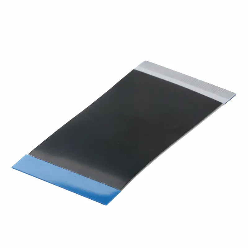
A shielded FFC (Flexible Flat Cable) only reduces EMI when the foil shield is grounded correctly. In LVDS systems—especially in medical devices where emissions and immunity margins are tight—many “shielded cable still fails EMI” cases come from high‑impedance shield termination or gaps at the connector interface.
This guide focuses on foil‑shielded FFC grounding: what to build, where it fails, and how to validate it before compliance testing.
Key Takeaways (What to do first)
- Use a short, wide, low‑impedance bond between foil shield and chassis/ground reference (not a thin pigtail).
- Eliminate connector transition gaps—these act like slot antennas and can spike radiated emissions.
- For LVDS, treat grounding as a return‑path and common‑mode control problem, not “add more shield” only.
- If the cable flexes, verify shielding after bending cycles (foil can crack and lose continuity).
1) When you actually need shielded FFC grounding improvements
Typical LVDS EMI/EMC symptoms include:
- Display flicker/noise or intermittent link issues near motors, SMPS, or RF modules
- Radiated emissions peaks increase when the FFC is attached
- Failures cluster around the connector/cable entry area
- Touching the shield or chassis changes the noise (a strong hint of poor termination)
2) Why foil shielding fails without proper grounding (in plain engineering terms)
Foil provides excellent E‑field shielding at high frequencies only if induced currents can flow to a stable reference. If the foil shield is floating or bonded through a long narrow path, it becomes a high‑frequency radiator rather than a sink.
What matters most is not “DC continuity”, but high‑frequency impedance:
- Long, thin bonds = high inductance = poor HF grounding
- Wide, direct bonds = lower inductance = effective HF grounding
3) Step‑by‑step: How to ground a foil‑shielded FFC for LVDS
Step 3.1 — Choose the grounding reference (PCB ground vs chassis)
For medical devices, a common best practice is:
- Bond shield primarily to chassis/earth reference (if available and well‑defined)
- Keep LVDS signal return behavior stable (avoid unpredictable current paths across sensitive analog areas)
If your device has no true chassis/earth, you can bond to a “quiet” ground region—just ensure the path is short and does not route shield currents through sensitive circuits.
Step 3.2 — Terminate the foil shield with a wide, repeatable contact
Recommended termination options for foil‑shielded FFC:
- Conductive stiffener grounding (strongly recommended)
- Use a conductive stiffener so the foil shield contacts a large ground pad/frame area.
- Ensure direct metal‑to‑metal contact; avoid relying on solder mask edges or tiny pads.
- Grounding tabs / clamps near the connector
- Add a mechanical tab or clamp that bonds the shield to chassis/ground with wide contact.
- Avoid long “tails” or thin wires.
- Dedicated connector ground pins + layout strategy
- Place multiple GND pins adjacent to LVDS pairs when possible.
- Keep the ground connection close to the connector to minimize loop area.
Practical target: make the shield bond physically as short and wide as possible. If you can reduce bond length from “centimeters of trace” to “direct contact at the connector”, EMI results often improve immediately.
4) One‑end or both‑end grounding for shielded FFC? (LVDS‑oriented guidance)
Users search this exact question—here is a practical answer.
Prefer both‑end bonding when:
- Your problem is radiated emissions (common in LVDS cable/connector zones)
- You have a stable reference (chassis or well‑managed system ground) at both ends
- You need maximum high‑frequency containment
Consider one‑end bonding when:
- The system has large ground potential differences between ends
- You see evidence of low‑frequency loop currents (audible noise, low‑freq interference paths)
Medical LVDS reality: many EMI failures are high‑frequency related, so starting with both‑end bonding (implemented correctly with wide/short termination) is often the fastest path to improvement. If ground loop concerns exist, solve them with a system grounding strategy—not by leaving the shield floating.
5) The #1 hidden EMI killer: Connector “slot antenna” gaps
Even with foil shielding, small discontinuities near the connector can act like slot antennas.
Common causes:
- Foil shield is pushed back during assembly
- The foil does not reach the connector interface
- The shield termination contact is intermittent or too narrow
- Exposed openings at the transition between cable and connector
Fix checklist:
- Extend shield coverage as close to the connector interface as possible
- Add conductive tape/overwrap at the transition to close openings
- Ensure the termination provides consistent contact over tolerance and vibration
6) Foil shield + LVDS signal integrity: grounding is also a return‑path problem
LVDS is differential, but EMI often comes from common‑mode conversion caused by:
- impedance discontinuities
- asymmetry at transitions
- poor reference/return path control near the connector
What helps:
- consistent pair geometry and spacing
- stable reference near the connector
- grounded shield termination that reduces common‑mode current on the cable
If you only “add shield” without controlling the termination and interface symmetry, you may not reduce emissions.
7) Quick reference: Why foil is usually chosen (and when it’s not)
| Shield option | Best for | Watch‑outs |
|---|---|---|
| Aluminum foil (single/double) | High‑frequency E‑field shielding, thin profile (common in compact medical modules) | May crack under repeated bending; termination quality is critical |
| Braided/mesh shield | Better mechanical durability; can help more at lower frequencies | Thicker; needs space and careful termination |
| Controlled‑impedance design | LVDS stability and SI (reduces reflections/common‑mode) | Shield alone won’t fix impedance mismatch; geometry matters |
8) Pre‑compliance EMI checklist (fast, practical)
Before formal testing, verify:
- Shield is grounded with wide contact (stiffener/tab/clamp), not a thin pigtail
- No visible shield gaps at the connector transition (slot antenna risk)
- Ground pins near LVDS pairs (if connector allows), short return path
- Shield continuity verified after assembly (and after flex cycles if moving)
- Cable routing avoids large loops and proximity to strong noise sources (SMPS inductors, motors)
FAQ
Why does a “shielded” FFC still fail EMI?
Most often the foil is not terminated with a low‑impedance bond, or there is a connector gap acting as a slot antenna. A floating/high‑impedance shield can re‑radiate noise.
Is foil shielding enough for LVDS in medical devices?
Foil shielding can be very effective for high‑frequency E‑field noise, but only with proper grounding and a clean connector interface. For dynamic flexing, validate durability because foil can crack.
Should the shield be grounded to PCB ground or chassis?
For emissions control, bonding to chassis (when available) is common. The key is using a stable reference and keeping the termination short and wide.
How do I reduce EMI at the connector area?
Treat the connector transition as the highest‑risk zone: minimize shield gaps, avoid narrow/long ground bonds, and ensure consistent contact and symmetry around the LVDS pair interface.
Typical LVDS Medical Applications (Where EMI issues often appear)
Foil‑shielded FFC cables are commonly used in compact medical electronics where space is limited but EMC requirements are strict, such as:
- Patient monitors and bedside displays (LVDS display interconnects)
- Portable ultrasound systems (noisy power rails + dense layout)
- Endoscopy/inspection systems (tight mechanical assemblies and long cable routing)
- Medical carts and diagnostic equipment with multiple boards and harnesses
In these systems, EMI risk often concentrates at the FFC connector area, where small shield discontinuities or high‑impedance bonds can turn into measurable radiated emission peaks.
Want a grounding recommendation for your exact LVDS stack-up?
If you share the details below, we can suggest a practical foil‑shielded FFC grounding approach (stiffener/tab/ground pin scheme) that typically reduces connector‑area emissions and improves test stability:
- LVDS interface (resolution, refresh rate, approximate data rate)
- Cable length and whether the cable is static or flexing during use
- Connector pitch and pin count
- Grounding reference preference (chassis/earth available or PCB ground only)
- The specific EMI symptom (radiated peak near connector, display artifacts, intermittent link, etc.)
With these inputs, we can recommend:
- one‑end vs both‑end bonding strategy to start with
- shield termination geometry (short/wide contact style)
- connector transition treatments to avoid slot‑antenna gaps
