
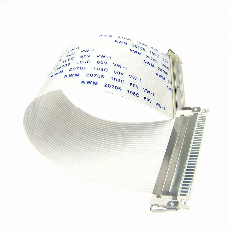
Choosing the correct FFC (Flexible Flat Cable) contact orientation is a basic but critical step in electronics design and assembly. If the exposed copper pads face the wrong direction, a single-sided ZIF connector may clamp the insulation instead of copper, causing a complete open circuit. In worse cases, the cable orientation mirrors the pinout and routes power to the wrong pins, creating power-to-ground shorts and permanent board damage.
This guide explains how to identify FFC contacts up vs down, the difference between Type A (same-side) and Type D (opposite-side), and how to match them to top-contact vs bottom-contact ZIF connectors.
Introduction
- Decide contact orientation first: Type A (same-side) vs Type D (opposite-side).
- Match the exposed copper pads to the connector terminal side (top-contact or bottom-contact).
- Don’t “fix” orientation by twisting the cable—this can crack copper conductors and create intermittent faults.
- Always verify Pin 1 on the cable and PCB before locking the ZIF latch.
Structural Differences in FFC Contacts Orientation
FFC Contact Orientation Guide: Contacts Up vs Down (Type A vs Type D) for ZIF Connectors
Choosing the correct FFC (Flexible Flat Cable) contact orientation is a basic but critical step in electronics design and assembly. If the exposed copper pads face the wrong direction, a single-sided ZIF connector may clamp the insulation instead of copper, causing a complete open circuit. In worse cases, the cable orientation mirrors the pinout and routes power to the wrong pins, creating power-to-ground shorts and permanent board damage.
This guide explains how to identify FFC contacts up vs down, the difference between Type A (same-side) and Type D (opposite-side), and how to match them to top-contact vs bottom-contact ZIF connectors.
Key Takeaways
- Decide contact orientation first: Type A (same-side) vs Type D (opposite-side).
- Match the exposed copper pads to the connector terminal side (top-contact or bottom-contact).
- Don’t “fix” orientation by twisting the cable—this can crack copper conductors and create intermittent faults.
- Always verify Pin 1 on the cable and PCB before locking the ZIF latch.
30-Second Quick Check (Most searched: “contacts up or down?”)
Use this quick method before ordering or inserting the cable:
- Look into the connector slot on the PCB
- If the metal spring terminals are on the “top wall” of the slot → it’s a top-contact connector
- If the metal spring terminals are on the “bottom wall” of the slot → it’s a bottom-contact connector
- Check the cable end you will insert
- The exposed copper pads must face the connector terminals
- If you see only smooth plastic film facing the terminals → you will get an open circuit
- Check the other end of the cable
- If both ends need copper facing the same way → choose Type A (same-side)
- If one end must face up and the other must face down → choose Type D (opposite-side)
If any step is unclear, stop before locking the latch and confirm with the connector datasheet or assembly drawing.
1) What “contact orientation” means on an FFC
An FFC is made of flat copper conductors laminated between insulation films (often PET). At both ends, the insulation is removed to expose copper pads for connector mating.
“Contact orientation” describes where those exposed pads are located:
Type A (Same-side contacts)
- Exposed pads are on the same face at both ends (top-to-top or bottom-to-bottom).
- Use Type A when your connector arrangement needs copper facing the same direction at both ends.
Type D (Opposite-side contacts)
- Exposed pads are on opposite faces at the two ends (top-to-bottom).
- Use Type D when your mechanical layout requires a face flip without twisting the cable.
Practical rule:
If your assembly needs “contacts up” at one connector and “contacts down” at the other, specify Type D.
2) Top-contact vs bottom-contact connectors (what to match)
Single-sided ZIF connectors contact the cable from only one side:
- Top-contact: terminals touch the cable from above
- Bottom-contact: terminals touch the cable from below
If the copper pads do not face the terminal side, the connector clamps insulation film → no electrical contact.
Fast matching table
| PCB connector type | Copper pads should face | If inserted wrong |
|---|---|---|
| Top-contact ZIF | Up (toward top terminals) | Open circuit |
| Bottom-contact ZIF | Down (toward bottom terminals) | Open circuit |
| Dual-contact ZIF (both sides) | Either | Fewer mistakes, but higher cost/size; may add capacitance |
3) What goes wrong when orientation is wrong
3.1 Open circuit (insulation-to-terminal contact)
The most common failure. The device simply won’t work because the connector is pressing plastic film instead of copper pads.
Symptoms:
- no power to downstream board
- no display, no response, no communication
- intermittent behavior if partially inserted
3.2 Mirrored pinout (Pin 1 becomes the last pin)
Type A vs Type D mismatch can mirror the pin order end-to-end.
Symptoms:
- LVDS pairs swapped or split
- control lines miswired
- boot failures, bus errors, random resets
3.3 Power-to-ground short (worst case)
If a power pin lands on a ground pin due to mirrored mapping, you can create an immediate short on power-up.
Possible damage:
- burnt regulators
- blown fuses
- overheated traces/connectors
- damaged ICs and PCB
4) Don’t twist the cable as a workaround
Twisting an FFC to flip the contact side is risky because it:
- creates stress concentration at the copper/film interface
- increases chance of copper cracking after repeated movement or vibration
- pulls on ZIF latches and reduces long-term contact reliability
Correct approach:
- specify the correct orientation (Type A or Type D), or
- use a custom folded/formed cable designed for your routing path
5) Stiffeners: the hidden factor affecting insertion and reliability
Stiffeners reinforce the cable end to:
- improve insertion depth control
- distribute clamping force
- reduce bending at the exposed pad region
Best practice:
- ensure the stiffener thickness matches connector requirements
- keep the cable flat and fully seated before closing the latch
6) Assembly + QA checklist (use on the bench and on the line)
Before locking the ZIF latch:
- Confirm connector type: top-contact or bottom-contact
- Confirm cable type: Type A or Type D
- Verify Pin 1: cable marking aligns with PCB silkscreen
- Verify copper-to-terminal contact: pads face the terminals
- Fully seat the cable: straight and inserted to the stop line (if present)
Before applying full power:
- continuity check on at least: power, ground, and one signal pin/pair
- quick resistance check to detect power-to-ground short
FAQ
“FFC contacts up or down” — what does it mean?
It describes which face of the cable has exposed copper pads at the connector end. The copper pads must face the connector terminals (top-contact or bottom-contact) to make electrical contact.
What is the difference between Type A and Type D FFC?
Type A has pads on the same face at both ends. Type D has pads on opposite faces at the two ends (one end up, the other down).
Why does my ZIF connector show open circuit after insertion?
Most likely the cable is flipped so insulation faces the terminals, or the latch is not fully locked, or the cable is not fully seated.
Can wrong FFC orientation really cause a short circuit?
Yes. If the pin order becomes mirrored, power and ground can land on the wrong pins, causing a power-to-ground short at power-up.
How do I avoid mistakes in production?
Use clear Pin 1 markings, PCB silkscreen triangles, incoming inspection of cable orientation (Type A/Type D), and a simple pre-power continuity/short test.
Need help confirming Type A vs Type D (Contacts Up/Down)?
If you’re not 100% sure whether your connector is top-contact or bottom-contact, send us the details below and we can confirm the correct FFC orientation (Type A vs Type D) and the safest assembly direction before you place an order:
- A clear photo of the PCB connector (side view looking into the slot is best)
- Connector pitch and pin count (e.g., 0.5mm, 30 pins)
- Cable length and whether the cable will be static or repeatedly flexed
- Which end is Pin 1 on your PCB (photo of silkscreen marking helps)
- Your application (LVDS display, camera module, control board, etc.)
Based on this, we can recommend:
stiffener style and reinforcement options to reduce mis-insertion and improve long-term reliability
the correct contact orientation (same-side or opposite-side)
insertion direction (contacts up or down) for your connector
