
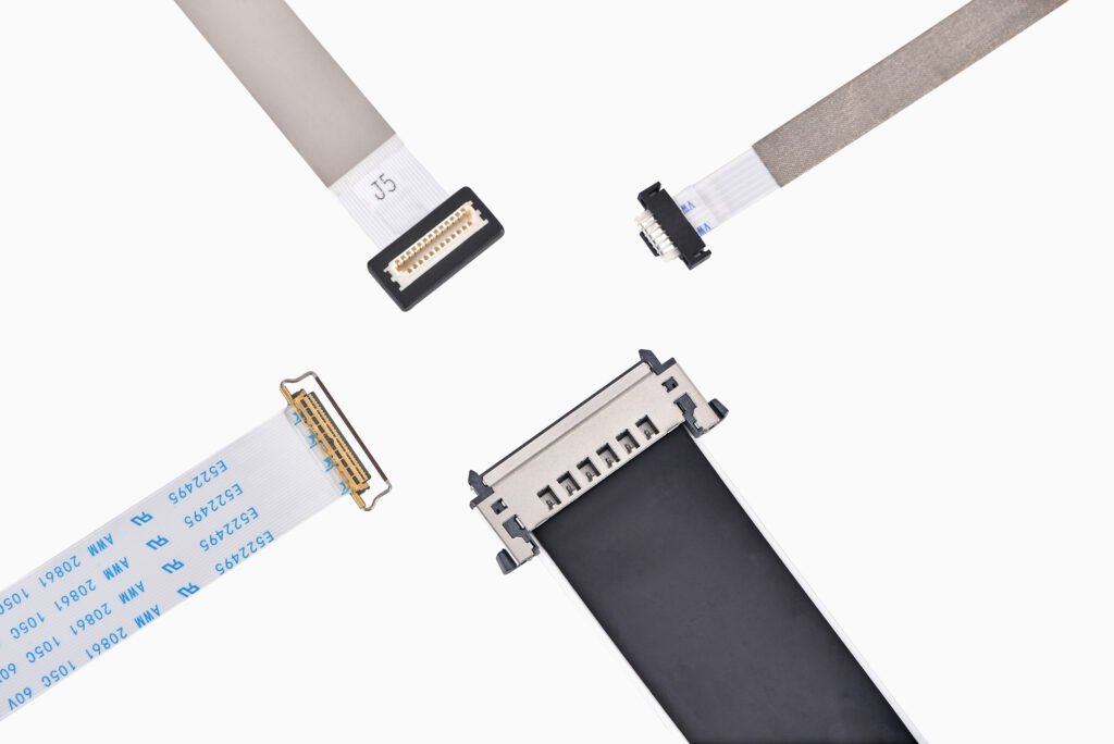
FFC cables fail due to multiple root causes of FFC cable breakage/bad contact across categories: bending radius, stress, locking mechanism, and contamination. Each cause produces either conductor breakage or intermittent bad contact. Technicians should check routing, lock connectors, and clean contact surfaces during assembly. This guide reviews each cable assembly failure cause including failure mechanism, real-world scenario, failure type, prevention steps, and inspection tip. Knowing these root causes of FFC cable breakage/bad contact helps stop early failure in cable assemblies. One cable assembly failure can stop production or lower device performance. Good handling greatly lowers risk.
Key Takeaways
Follow the minimum bend radius rules. Use the formula R equals T times N. This step keeps tight bends from breaking conductors.
Spread flexing over the whole cable. Secure cables at regular spots. This reduces fatigue from repeated bending at one point.
Grip the connector body, not the cable. Don’t twist the cable while putting it together. Use strain relief to keep the conductor joints safe.
Check the actuator latch closes fully. Replace worn connectors fast. Clean contacts with lint-free swabs before assembly.
Protect contacts from moisture and chemicals. Use sealed connectors and apply conformal coating. This prevents corrosion and extends the cable life.
Bend Radius Failures: Causes #1 and #2
Cause #1: Inadequate Bend Radius
A bend radius that is too small is a top reason FFC cables break. When a flexible flat cable bends too sharply, the copper conductors on the outer curve get stretched. The ones on the inner curve get squeezed. This mechanical strain weakens the conductor traces over time. In the end, a conductor strand breaks, and the circuit stops working. The root causes of ffc cable breakage/bad contact all lead to either breakage or bad contact. Inadequate bend radius is at the top of that list.
Minimum bend radius is the tightest curve a cable can take without damage. Think of it as the smallest arc the cable can safely follow. IPC-2223 gives clear guidance for flexible flat cables. Single-sided and double-sided flexible circuits need a minimum static bend radius of at least 6 times the total thickness. Multilayer flexible circuits need at least 12 times the total thickness. For dynamic applications, the rule of thumb is about 10 times the total thickness. This can vary by manufacturer, though.
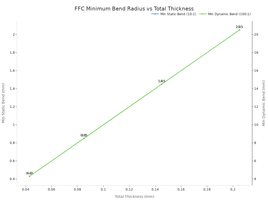
The formula R = T × N helps engineers figure out the safe bend radius. Here, R is the bend radius, T is the total cable thickness, and N is the bend ratio. For static single-layer applications, N equals 10. For single-layer dynamic applications, N equals 100. Only rolled-annealed copper should be used in dynamic applications.
Copper Thickness | PI Thickness | Total Thickness | Min Static Bend (10:1) | Min Dynamic Bend (100:1) |
|---|---|---|---|---|
18 µm | 25 µm | 0.043 mm | 0.43 mm | 4.3 mm |
35 µm | 50 µm | 0.085 mm | 0.85 mm | 8.5 mm |
70 µm | 75 µm | 0.145 mm | 1.45 mm | 14.5 mm |
105 µm | 100 µm | 0.205 mm | 2.05 mm | 20.5 mm |
Flexible flat cables can be made with flexible routing in mind. These products help designers stay within bend radius limits during installation. Proper routing stops early failure in cable assemblies.
Cause #2: Repeated Flexing at One Point
Repeated flexing at one point is another cause of bend radius failures. This problem happens when a cable bends back and forth at the same spot. Too much bending at a single spot creates fatigue in the copper conductors. The metal finally cracks, and the cable assembly failure comes next. This type of damage often shows up in devices with moving parts, like hinges or sliding mechanisms.
Designers should spread bending along the cable length. They should also secure the cable to stop motion at fixed points. A cable assembly that flexes at one point will fail much sooner than one that flexes evenly. Cables with flexible routing can spread stress across the cable. This design choice lowers the risk of early failure in cable assemblies.
Technicians should check cables for sharp kinks or repeated bend marks. Any visible crease means there is a bend radius problem. Fixing the routing early stops conductor fatigue and makes cable life longer.
Stress-Induced Cable Assembly Failure Causes
Cause #3: Tensile Pull and Cause #4: Torsional Twist
Tensile pull happens when someone pulls the cable instead of the connector during installation or removal. This puts mechanical stress right on the conductor traces. The copper traces stretch and get thin. In time, a trace breaks, and the circuit stops working. Technicians should always hold the connector body, not the cable itself.
Torsional twist happens when the cable turns along its length. This twisting motion puts uneven mechanical stress across the conductors. The outer traces feel more strain than the inner ones. Over time, this uneven loading causes conductor fatigue and breakage. Designers should route cables so they avoid any twisting motion during assembly or device operation.
Inadequate strain relief makes both problems worse. A cable without proper strain relief sends all pulling and twisting forces straight to the conductor terminations. The solder joints or crimp connections carry the full load. These joints crack under repeated mechanical stress. Adding strain relief features spreads these forces away from critical connection points.
Cables designed for high-vibration and EMI-sensitive applications handle these concerns. These products use reinforced constructions that resist tensile and torsional forces. Picking the right cable lowers the risk of early failure in cable assemblies.
Cause #5: Vibration Fatigue
Vibration fatigue is another cause of stress-induced cable assembly failure. This problem grows in applications with constant motion or vibration. Vehicles, industrial equipment, and portable devices all make vibration during normal operation. The cable vibrates at high frequency, and the conductors go through repeated mechanical stress cycles.
Each vibration cycle bends the conductor a little. The metal goes through tiny changes at the grain level. After many repeated cycles, small cracks form. These cracks grow until the conductor breaks all the way. The failure often shows up as an intermittent bad contact before total breakage happens.
The bend radius plays a key role in vibration fatigue. A cable routed with a tight bend radius puts mechanical stress all at the bend point. A cable routed with a generous bend radius spreads stress along a longer section. This spread makes cable life much longer.
Cables built for high-vibration environments resist fatigue from constant motion. Cables designed for EMI-sensitive applications give similar durability. These products help stop early failure in cable assemblies.
Designers should secure cables at regular intervals to control vibration amplitude. They should also avoid routing cables near vibration sources when possible. Proper mounting and routing cut down the mechanical stress that leads to conductor fatigue.
Technicians should check cables in high-vibration applications more often. They should look for cracked insulation, exposed conductors, or intermittent signal issues. Finding problems early prevents complete cable assembly failure and unexpected downtime.
Knowing these mechanical causes of early cable assembly failure helps engineers design more reliable systems. Tensile pull, torsional twist, and vibration fatigue all lead to the same result: conductor breakage and bad contact. Proper routing, enough strain relief, and the right cable choice prevent these outcomes. Engineers who deal with these stress factors make cable life longer and improve product reliability.
Locking Mechanism Failures: Causes #6 and #7
Cause #6: Incomplete Latch or Actuator Closure
An incomplete latch closure is one of the root causes of ffc cable breakage/bad contact. This problem happens when the actuator on an ffc/fpc connector does not close all the way. The cable sits loose inside the connector housing. Signal loss follows. A technician may push the actuator down and feel a click. That click does not always mean full closure. Partial closure leaves the contacts floating. The result is intermittent connections that come and go with vibration or temperature changes.
Improper alignment makes this problem worse. A cable inserted at a slight angle pushes against the actuator. The latch cannot seat correctly. Operators should insert the cable straight and verify the actuator sits flush with the connector body. A quick pull test confirms proper seating. The cable should not slide out with light tension.
Connector designs can allow easy rework without damaging the contacts. Technicians can remove and reinsert the cable multiple times. Proper locking prevents bad contact and intermittent signal loss.
Cause #7: Worn or Damaged Locking Mechanism
A worn or damaged locking mechanism is another cause of premature failure in cable assemblies. Latching mechanisms lose holding force after many insertion cycles. Plastic actuators crack or break. Metal springs lose tension. A damaged latch cannot hold the cable against the contacts. Loose contacts create resistance changes and signal dropouts.
Manufacturing and assembly defects contribute to this problem. Poor crimping and termination quality weakens the connection between the cable and connector. A weak termination cannot handle repeated mating cycles. Intermittent failures appear more often as the connector ages.
Technicians should inspect latching mechanisms during every service interval. They should look for cracks, discoloration, or loose movement. A latch that moves too freely signals wear. Replacing the connector before total failure prevents premature failure in cable assemblies. Proper handling during assembly also extends connector life. Connector design can support repeated mating cycles. This reliability reduces premature failure in cable assemblies across the product lifespan.
Contamination Failures: Causes #8 and #9
Cause #8: Dust and Debris on Contacts
Dust and debris on contacts is one of the root causes of ffc cable breakage/bad contact. During assembly or normal use, particles land on the open contact pads of an ffc/fpc connector. These particles get trapped between the cable tail and the connector terminal. This shrinks the contact area, so resistance builds up at that spot. The signal gets weaker or cuts out completely. Even tiny particles of dust can make connections appear and vanish without notice.
Factories often have tiny particles floating in the air. Paper fibers, skin flakes, and solder dust can land on open connectors. Technicians should keep connector areas covered until the cable goes in. They should also clean contacts with lint-free swabs and approved solvents before connecting. A quick check under a magnifier reveals dirt the naked eye misses. Cables built for clean signal integrity work well in these applications. These products help engineers avoid contamination-related causes of early cable assembly failure.
Cause #9: Moisture or Chemical Residue Causing Corrosion
Moisture and chemical residue cause another failure mode. When temperature changes, water vapor condenses on the contact surfaces. Flux left after soldering forms a chemical film. Both damage the metal plating on the contacts. The plating corrodes and creates an oxide layer. This layer blocks current and makes contacts loose or oxidized. The result is a slow drop in signal quality, then a full cable assembly failure.
Corrosion grows faster in humid or chemical-heavy settings. Automotive, medical, and industrial devices face these conditions every day. Designers should pick sealed connectors or use conformal coating on exposed contact areas. Technicians should clean flux after soldering and store cables in dry spots. Cable designs for stable contact performance stand up to these environments. Good cleaning and sealing stop contamination from causing intermittent failures. These steps also lower the chance of early cable assembly failure. They extend service life and protect signal quality over the product’s life. Careful handling at every stage stops early cable assembly failure before it starts.
The main reasons FFC cables break or have bad contact each have a clear fix. Use this checklist:
Cause | Corrective Action |
|---|---|
Bend radius too small | Route with wide, gentle curves |
Flexing in one spot | Spread bending along the whole length |
Pulling on the cable | Hold the connector, not the cable |
Twisting the cable | Avoid twisting it during assembly |
Vibration fatigue | Secure the cable at regular points |
Latch not fully closed | Check the actuator sits flush |
Worn locking mechanism | Replace connectors that are worn out |
Dust and debris | Clean with lint-free swabs |
Moisture and chemicals | Seal it and store it dry |
Check your current FFC designs, assembly steps, and connector choices today. Most cable assembly failure can be prevented with the right routing, locking, and cleaning. Mechanical stress and other stress factors go down when teams follow these steps. Custom FFC solutions developed with OEMs can tackle these root causes and cut down early failure in cable assemblies.
FAQ
What is the minimum bend radius for an FFC cable?
The minimum bend radius changes with cable thickness and use. For static single-layer use, the ratio is 10:1. For single-layer dynamic use, the ratio is 100:1. Designers multiply the thickness by the ratio. A tight bend radius stretches copper traces and causes breakage.
How many insertion cycles can a ZIF cable endure?
These cables can handle repeated insertion cycles. If the locking mechanism is worn, lifespan drops. Inserting the cable straight prevents early failure in cable assemblies. Technicians should check latches during maintenance and replace worn connectors promptly.
Why does dust cause bad contact?
Dust can get between the cable tail and connector terminal, shrinking the contact area. Resistance builds there, so signals weaken, drop out, or come and go from even tiny particles. Lint-free swabs and approved solvents remove debris before assembly. This stops contamination from causing cable assembly failure.
What causes manufacturing and assembly defects?
Poor crimping, bad alignment, or a latch left half-open can cause early failure. These defects lead to loose contacts and on-and-off signals. Operators should check that the actuator sits flat and pull-test every connection. Careful handling during assembly prevents these problems.
How does routing prevent vibration fatigue?
Routing with a wide bend radius spreads stress along the cable. A bigger bend radius lowers stress at fixed points. Fastening cables at regular intervals limits vibration. Cables can be made to resist fatigue from motion. Proper routing reduces some of the root causes of ffc cable breakage/bad contact.
