
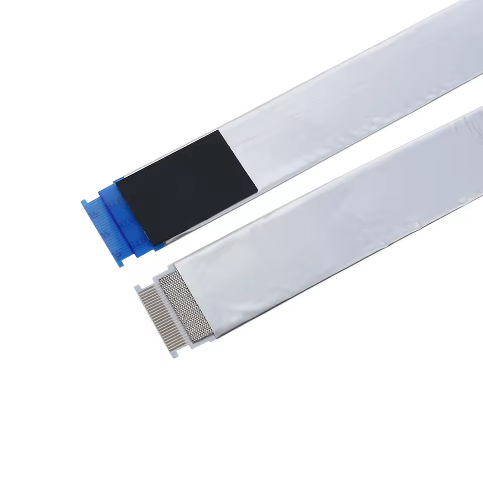
Engineers face three main choices during shielded FFC selection: how to ground it, what shield structure to use, and what EMI problems to avoid. Each choice affects signal quality, cost, and how hard it is to assemble.
The short answers are simple. Connect both ends with wide, low-resistance links. Pick foil or copper shielding based on the frequency you use and how much the cable must bend. Stay away from connector gaps and pigtail bonds that weaken the shield.
This guide gives shielded FFC selection rules, steps to follow, and troubleshooting checks that teams can use right away on real designs. Readers will find clear rules for matching shield types to their needs, ending shields the right way, and finding common EMI failures before they reach production.
Key Points
Ground both shield ends with wide, short bonds. These bonds keep inductance low. This setup drains noise. It prevents radiation.
Choose foil for tight bends. Choose copper braid for strict emission limits. Choose a grounded copper plane for high-speed pairs.
A drain wire adds inductance at high frequencies. Long pigtails create voltage drops. Avoid these parts for high-speed lines.
Connector gaps act like antennas. Pigtail bonds weaken the shield. These gaps cause radiated emissions. Use full-perimeter contact.
Plan grounding geometry early. Use every shield pin. Use multiple vias. Choose single-end grounding only for ground loops.
Shielded FFC Selection: Quick Answer
Engineers need fast answers before they look at stackups. Grounding controls how well a shield works. Shield structure sets flexibility and frequency range. A grounded copper layer built into the flex stackup gives the strongest EMI protection. These choices decide if the cable passes or fails an EMI test.
Grounding Methods at a Glance
Bond both ends of the shield with wide, short, low-impedance connections. This method drains caused noise from nearby motors and radio transmitters. It also stops the shield from radiating like an antenna. Single-end grounding works as a backup only when both-end bonding causes ground loops between distant modules. In that case, ground the shield at the receiving end and leave the other end isolated. A common mistake assumes a drain wire gives a low-impedance path. In reality, a drain wire adds inductance at high frequencies and weakens shielding performance.
The physical shape of the ground connection sets its quality. A wide planar connection keeps inductance low at high frequencies. A long pigtail or narrow trace creates a voltage drop and weakens shielding effectiveness. Designers should place ground bond points as close to the connector shield pins as possible. The ground strap should match the width of the cable’s shield layer. If the connector offers multiple shield pins, use them all. When the strap connects to a PCB, use multiple vias to tie it to an internal ground plane.
Shield Structures at a Glance
Foil shielding adds very little thickness and keeps cable flexibility. Single-sided aluminum foil blocks low-frequency noise and fits into tight bends. Double-sided foil gives continuous coverage on both surfaces and works for moderate-frequency EMI. Conductive film offers another lightweight option but gives less reliable grounding continuity than metal layers. Foil shielding stays popular for automotive and medical devices because it meets cost targets while keeping the cable’s thin profile.
Copper layers form a stronger shield. A grounded copper plane built into the stackup gives some of the most robust protection for flex circuits because it provides a solid return path directly under the signal traces. Hybrid structures combine foil with braided copper mesh when a cable must meet strict radiated-emission limits. These hybrids trade flexibility for wider frequency coverage. They also add cost and reduce the minimum bend radius compared with foil alone. For high-speed differential pairs, a continuous copper plane beats any foil alternative. The best Shielded FFC selection matches the shield structure to the noise spectrum, mechanical bending requirements, and assembly cost.
When Shielding and Grounding Are Needed
Signal and Environment Triggers
High-frequency signals need shielded FFCs. Regular unshielded ribbon cables work fine for low-frequency signals under 100 MHz. These cables are good for short runs under 10 cm when kept away from noise sources. Engineers should switch to EMI-shielded FFCs for high-speed digital signals like LVDS or DSI. Longer runs over 15 cm also need shielding. Being close to motors and switching power supplies is another reason. Confirmed EMI symptoms like jitter or CRC errors show that shielding is needed.
Cable type | Frequency guidance | Run length / EMI conditions |
|---|---|---|
Standard (unshielded) FFC | Suitable for low-frequency signals below 100 MHz | Short runs under 10 cm; isolated from noise sources |
EMI-shielded FFC | Needed for high-speed digital signals such as LVDS/DSI | Longer runs over 15 cm; proximity to motors/switchers; verified EMI symptoms such as jitter or CRC errors |
Standard FFC ribbon cables do not have a conductive shielding layer. This design leaves them open to outside EMI and RFI in noisy electromagnetic places. Signal degradation and impedance mismatches can happen. Shielded FFCs become necessary when nearby EMI source levels are high enough to cause this kind of interference. Wireless modules and RF components also raise the noise floor. Shielding is recommended when signal degradation could come from EMI, crosstalk, or transient voltages.
When Shielding Is Overkill
Shielding adds cost and stiffness without real benefit in some cases. Low-speed digital lines and simple power connections almost never need shielding. Short cable runs inside a well-grounded enclosure also fall into this group. If the cable works far from motors, wireless modules, and RF components, shielding may not help performance. Engineers should measure actual noise levels before adding shielding. A design that passes EMI testing without shielding saves money and keeps the cable flexible.
Adding shielding to every cable makes assembly more complex. It also reduces the minimum bend radius. For applications with tight routing or frequent flexing, unshielded FFCs often work better. The key is matching the cable to the real electromagnetic environment. Teams should check whether signal degradation happens before committing to a shielded design.
Grounding Methods for Shielded FFCs
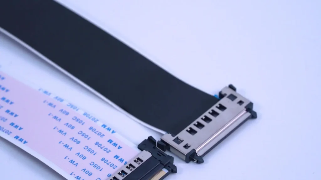
Good shielding depends on the grounding setup just as much as the metal layer. A low-impedance ground path pulls away noise currents and keeps the shield from acting like an antenna. Without a strong path, the shield picks up interference and sends it back out. Engineers must choose where to bond the shield, how wide the connection should be, and whether the design can handle a full wrap-around termination.
Both-End vs. Single-End Grounding
Both-end grounding is the best place to start. Connect the shield to ground at both ends, close to the connector shield pins. This setup makes a short return loop. It drains common-mode noise from nearby motors, wireless modules, and switching supplies. It also keeps the voltage steady along the cable when both modules share the same ground plane. Both-end bonding works well in most automotive, medical, and industrial layouts because the cable sits inside a chassis with a solid reference.
Before picking a method, engineers should map the ground planes. A single chassis ground works with both-end bonding. Separate power domains with different reference voltages need a different approach. In that case, single-end grounding is a backup, not a first choice. Engineers should use it only when both-end grounding causes a ground loop between distant modules. For example, a sensor unit and a controller may have separate power grounds at different voltages. Connecting the shield at both ends lets current flow through the loop and creates noise. Grounding only at the receiving end breaks that loop. The far end stays quiet. The trade-off shows up at high frequencies: an open shield end loses some effectiveness because it cannot drain high-frequency noise as well. Single-end grounding fits low-speed or short connections, while both-end grounding serves high-speed signals.
Low-Impedance and 360-Degree Bonds
The shape of the ground connection sets its impedance. A wide, short bond keeps inductance low. A long pigtail wire or a narrow trace adds inductance, where high-frequency noise needs a low-reactance path. The shield loses performance, and the cable can fail radiated-emissions tests. A drain wire, though common, is not a low-impedance connection. It acts like a small antenna at high frequencies. Designers should avoid it for high-speed lines.
For high-speed differential pairs, return current flows beneath the signal traces. If the shield opens at the connector, that return current detours through the pin field and increases loop area. Engineers should keep the shield continuous from the PCB ground plane through the connector shell.
360-degree termination is the best practice for shielded FFCs. It bonds the shield to the connector shell around the full perimeter, not just at one point. This continuous contact minimizes loop area and keeps the return path uniform. In a flex circuit, designers achieve this with conductive adhesive, copper foil wrapping, or solder pads that span the entire shield width. They should use every shield pin. They should place vias close to those pins and tie them into an internal ground plane. The ground strap ought to match the shield width, and the metal should extend to the edge of the cable. A careful Shielded FFC selection includes grounding geometry at the design stage, not as an afterthought. These details decide whether the cable passes EMI testing on the first attempt.
YLS Shielded-cable Structures
YLS Shielded-cable products come in four main types: single-sided aluminum foil, double-sided foil, braided copper mesh, and hybrid shielding. Each type fixes a different noise problem. Each one also changes how thick the cable is, how tightly it can bend, and how much it costs to build. Engineers who pick the right type for the job get better EMI results and need fewer design changes.
Foil, Film, and Copper Layers
Foil-based shielding barely adds any thickness and stays flexible. A single-sided aluminum foil layer blocks low-frequency noise and bends into tight curves. Double-sided foil covers both surfaces without gaps and handles moderate-frequency EMI. Foil-only shielding earns a Fair rating at low frequency (below 100 MHz) and an Excellent rating at high frequency (above 100 MHz), but it has poor flex life and mechanical durability. Designers who need the cable to flex many times should think about this trade-off carefully.
Silver ink and shielding films give you more choices for flex EMI shielding. Silver ink prints right onto the flex substrate and adds almost no thickness. Shielding films create a lightweight barrier for designs with little space. These materials give engineers more ways to control emissions without making the cable stiffer.
YLS Shielded-cable supports 90Ω–120Ω impedance control for LVDS, eDP, HDMI, and MIPI DSI/CSI signals. For LVDS constructions, the differential impedance is set at 85Ω with a tolerance of ±10%. This holds true for both shielded and unshielded versions. For shielded constructions made for LVDS, MIPI, HDMI, and eDP signals, the impedance-controlled shielded FFC allows a tolerance of ±10%. This tolerance covers characteristic impedance options of 90Ω (LVDS), 100Ω (USB), or custom values. Steady transmission across these high-speed interfaces depends on keeping that tolerance through the connector and cable assembly.
Drain Wire and Hybrid Designs
A drain wire gives you a simple ground path, but it adds inductance at high frequencies. Designers should see it as a convenience, not a high-performance solution. Hybrid designs mix foil with braided copper mesh when a cable must meet strict radiated-emission limits. The two layers work as a team. RF that slips through braid gaps gets blocked by foil, and low-frequency EMI that foil misses gets absorbed by braid.
Foil plus braid: the foil layer gives complete coverage; strength comes from both ends of the frequency range, and the braid gives a surface you can bond to. The foil covers the most but protects the least at low frequency, because shielding performance is set by conductance as well as coverage. Putting foil under a braid covers both ends of the frequency range and gives a surface that can be bonded around its circumference.
The performance gap can be measured. According to Telewire Tech, a hybrid foil-plus-braid construction usually reaches 60–90 dB attenuation across the 1 MHz to 1 GHz band, while a foil-only shield (or braid-only) reaches only 30–50 dB. The combined construction about doubles the shielding effectiveness of foil alone. Mesh braid gives better EMI performance but cuts down flexibility. A careful Shielded FFC selection weighs that performance gain against the mechanical limits of the routing path.
Step-by-Step Implementation
Stackup and Grounding Network
A grounded copper layer inside the flex stackup acts as a plane. It sits under the signal traces and gives return current a short, direct path. Engineers place this plane close to the signal layer. The tight spacing lowers loop area and cuts radiated emissions. A continuous plane also stabilizes impedance for high-speed lines.
The grounding network ties the shield to the system ground. Bond points belong near the connector shield pins. Multiple vias connect the shield layer to the internal ground plane. Every shield pin should carry a bond. The connector shell needs a full-perimeter termination, not a single point. This 360-degree contact keeps the return path uniform. A wide, short strap beats a long drain wire at high frequencies. Each of these details shapes a successful Shielded FFC selection.
Material and Routing Rules
Material choice follows the noise spectrum and the bend requirements. Foil suits tight routing and low-frequency noise. Braid handles strict emission limits but stiffens the cable. Conductive adhesive bonds the shield to the connector shell without solder. Silver ink and shielding films add lightweight options for space-limited designs.
Routing rules keep return paths short. Signal traces should run directly above the ground plane. Engineers avoid splits or slots in that plane. They route high-speed pairs away from motors and switching supplies. Ground stitching vias belong along the cable edges. These vias tie the shield layers together and stop resonance.
YLS Shielded-cable supports customization across pitch, pin count, and cable length. Pitch options span 0.5mm to 2.54mm. Pin counts range from 4 to 96 pins. Cable lengths run from 20mm to 10,000mm. Impedance control covers 90Ω to 120Ω for LVDS, eDP, HDMI, and MIPI DSI/CSI signals. Engineers can match the cable to the stackup and the routing path in one step.
Troubleshooting Common EMI Failures
Most shielding failures come from small engineering details. Poor grounding and gaps in the shield cause most of them. Engineers often miss a weak bond point or a tiny gap at the connector. Both create noise paths that hurt signal quality.
Intermittent Loss and High-Impedance Bonds
Intermittent signal loss usually means a high-impedance bond. A shield connection can show low DC resistance but still fail at high frequencies. The inductance of a long or narrow bond causes a voltage drop. That drop turns the shield into a small antenna that puts noise into signal lines. Random bit errors and jitter that come and go are typical.
Engineers should check every shield bond with a multimeter first. Measure DC resistance from the shield layer to the connector shell and to the PCB ground plane. A reading above a few milliohms means a poor connection. Inspect solder joints on all shield pins; cracked solder causes many intermittent failures. Conductive adhesive bonds break down with repeated flexing. A resistance check after thermal cycling finds weak bonds before production.
The fix means redesigning the bond geometry. Replace narrow traces with wide, short straps. Add stitching vias along the cable edge. Use every shield pin. A proper Shielded FFC selection includes these grounding details early in the design phase.
Radiated Emissions and Gaps
Radiated emissions come from gaps in the shield path. A connector that touches the shield at only one point leaves a slot that radiates like an antenna. Pigtail terminations cause the same problem. A long drain wire adds inductance and pushes high-frequency noise outside the cable. The shield then radiates instead of blocking.
Engineers should inspect the connector mating surface carefully. The shield must touch the connector shell around the full perimeter, not at a single spot. Foil shields need complete overlap at every seam. Any bare area between the foil edge and the connector shell opens an emission path. The shield must reach the cable’s edge; a short shield leaves inner conductors exposed.
A near-field probe quickly checks the design. Run the cable at full speed while moving the probe along the connector area. Spikes mark the gap locations. Fix those spots with wider shield contact and shorter ground connections. These checks turn a failing design into a passing one without a full redesign.
Shielded FFC Selection Trade-Offs
Cost, Flex Life, and Impedance
Foil shielding is the cheapest option and barely makes the cable thicker. It also keeps the cable easy to bend for tight paths. But foil-only designs have poor impedance control, and signals get weak past 1 meter. Copper braid costs more and meets strict emission limits. It also cuts bend life down to 5,000–10,000 cycles. Hybrid shielding mixes foil and braid to cover the widest frequency range. It costs the most and is the stiffest choice.
Shielding Type | Cost | Flex Life | Impedance Control |
|---|---|---|---|
Foil-only | Lowest | High flexibility | Poor beyond 1 m |
Copper braid | Moderate | 5,000–10,000 cycles | Limited |
Hybrid | Highest | Lowest | Best across frequency range |
A grounded copper layer built into the stackup gives the strongest impedance control for high-speed lines. Engineers should match the shield type to the frequency spectrum and how much the routing path must bend. A careful Shielded FFC selection weighs these three factors before locking in a design.
Assembly and Repairability
Foil-only cables work with ZIF connectors that need a small plastic tool to open and close the clamp. Non-ZIF versions need soldering or crimp terminals. Neither type has parts a user can service. Soldering or re-terminating FPC ends is not advised because the risk of damage is high. Cutting the cable ruins controlled impedance, so replacing it is safer and cheaper than fixing it.
Copper braid cables cost less but do not bend as many times. Hybrid cables need factory-terminated connectors and certified host ports. They cannot be repaired and must be fully replaced if damaged. Connector breakage is a top complaint. A non-ZIF connector on a low-cost FPC broke after 3 months of daily laptop docking. The fix was choosing 0.5mm-pitch ZIF variants.
YLS Shielded-cable offers factory-direct pricing and low minimum order quantities for prototyping and pilot runs. This lets teams test foil, braid, and hybrid options without a big upfront commitment.
Picking a shielded FFC comes down to three main things: how you ground it, what shield structure you use, and what problems you avoid. Engineers connect both ends with wide, short, low-resistance links. A specific reason, like a ground loop, can justify grounding only one end. They match the shield structure to frequency, flex life, and assembly limits. Foil works well for tight bends; copper braid meets strict emission limits. Hybrid designs cover the widest range but reduce flexibility.
Checking your work takes a checklist and real measurements. Guesses fail EMI tests. Teams inspect bond resistance, connector gaps, and shield continuity. Planning for EMI early prevents costly redesigns. Grounding geometry should be part of the stackup from the start. This approach turns shielded FFCs into reliable, compliant interconnect solutions.
FAQ
Can a shielded FFC use a drain wire instead of a full 360-degree bond?
A drain wire works as a convenience, not a high-performance solution. It adds inductance at high frequencies and acts like a small antenna. Engineers should use a full-perimeter bond with wide, short connections for high-speed lines.
Does foil shielding protect against both low and high frequency noise?
Foil blocks low-frequency noise well and adds minimal thickness. Its performance drops at higher frequencies. A hybrid foil-plus-braid design covers the full range and reaches 60–90 dB attenuation across 1 MHz to 1 GHz.
What impedance values can YLS Shielded-cable hold for high-speed interfaces?
YLS Shielded-cable supports 90Ω–120Ω impedance control with ±10% tolerance. This covers LVDS at 90Ω, USB at 100Ω, and custom values. The tolerance holds through the connector and cable assembly for eDP, HDMI, and MIPI DSI/CSI signals.
When does single-end grounding make more sense than both-end bonding?
Single-end grounding fits when both-end bonding creates a ground loop between modules with separate power grounds. Engineers ground the shield at the receiving end only. This method suits low-speed or short connections, not high-speed differential pairs.
How many flex cycles can copper braid shielding survive?
Copper braid cuts bend life to 5,000–10,000 cycles. Foil-only designs stay flexible for tight routing but offer poor impedance control past 1 meter. Hybrid shielding is the stiffest option. Engineers should match the shield type to the routing path’s bend requirements.
