
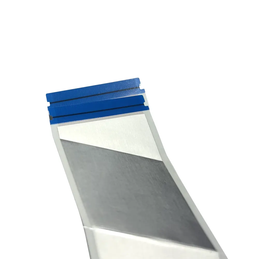
Shielded FFC or FPC is preferred for high-speed signal transmission due to its ability to control impedance, suppress electromagnetic interference (EMI), and reduce crosstalk. These characteristics are crucial for protocols such as LVDS, MIPI, eDP, or USB. Without shielding, high-frequency signals will rapidly attenuate, leading to data errors, system unexpected restarts, and even failure to pass FCC and CE compliance tests. These failures will result in time and cost losses. This article will explain the technical reasons behind this preference, helping you understand the manufacturing principles of shielded cables, their comparison with non-shielded cables, and the key factors to consider when choosing for a design.
Key Points
Shielded FFC/FPC can effectively manage signal transmission, suppress electromagnetic noise, reduce interference, and ensure stable transmission of high-speed data.
Unshielded cables will significantly deteriorate in performance when the speed exceeds 1 Gbps or the length exceeds 100 millimeters due to signal attenuation and noise influence.
Choose the appropriate shielding method based on the data transmission speed, cable length, and usage environment; the shielding layer should be grounded at both ends.
Shielded cables help reduce bit error rates and make it easier to meet the electromagnetic compatibility (EMC) requirements of devices such as LVDS and USB.
Why Shielded FFCs or FPCs Are Preferred for High-Speed Signals
The Physics of High-Frequency Signal Degradation
You might ask why a simple cable gets so tricky at high speeds. The answer is physics. When data rates go above 1 Gbps, signal rise times become very fast. A signal that switches from low to high in picoseconds acts differently than a slower one. At these speeds, even a short cable no longer works like a plain wire. It turns into a transmission line.
A transmission line has its own electrical traits. Every trace has inductance, capacitance, and resistance spread along its length. These traits matter little at low frequencies. At high frequencies, they take over. The signal does not just travel from point A to point B anymore. It interacts with the cable’s structure at every spot along the way.
Think of water moving through a pipe. At low pressure, the pipe’s shape hardly matters. At high pressure, every bend and narrow spot changes the flow. In the same way, at high frequencies, every change in the cable’s shape affects the signal. The conductor width, the insulation thickness, and the gap between traces all shape how the signal moves.
This is where impedance control becomes key. Impedance is the resistance to alternating current flow. For high-speed protocols like LVDS or MIPI, you need a specific impedance value. USB usually needs 90Ω. LVDS and MIPI often need 100Ω. When the cable’s impedance matches the system’s, signals pass cleanly. When they do not match, part of the signal bounces back toward the source. These bounces cause ringing, overshoot, and data errors.
Unshielded cables find it hard to keep steady impedance. Their shape shifts slightly along the length. Objects near the cable change its capacitance. This unevenness creates impedance breaks. Each break causes signal bounces. At high frequencies, even small bounces can push the signal past safe limits.
Core Threats: Crosstalk, EMI, and Impedance Mismatch
Three main dangers harm high-speed signals in unshielded cables. You need to know each one to see why shielding matters.
Crosstalk happens when energy from one trace jumps into a nearby trace. Every conductor gives off an electromagnetic field when current flows through it. At high frequencies, these fields get stronger. Nearby traces act like antennas, picking up this stray energy. The result? Your data signal gets mixed with noise from other signals. In a tight FFC with many parallel traces, crosstalk gets worse. The packed conductors leave little room between them, making the coupling even stronger.
Electromagnetic interference (EMI) comes from outside sources. Motors, power supplies, wireless transmitters, and other devices all give off electromagnetic radiation. An unshielded cable acts like an antenna. It picks up this outside noise and adds it to your signal. The noise ruins the data, causing bit errors. In cars or factories, EMI sources are everywhere. Your cable needs protection just to work in these places.
Impedance mismatch occurs when the cable’s characteristic impedance differs from the source or load impedance. This mismatch causes signal bounces. Each bounce wastes energy and twists the waveform. The eye diagram—a visual check of signal quality—closes up. Bit error rates go up. Your system may fail compliance tests completely.
Shielded FFCs or FPCs preferred for high-speed signals fix all three issues at once. The shielding layer acts like a Faraday cage around the conductors. This conductive barrier blocks outside EMI from reaching the signal traces. It also holds in the electromagnetic fields made by the signals themselves, stopping them from spreading out and causing crosstalk. The shield gives a steady ground reference that keeps impedance stable along the whole cable length. With good design, these cables keep steady impedance from one end to the other.
YLS high-speed cables support data rates up to 6 Gbps with controlled impedance options from 90Ω to 120Ω. This makes them good for MIPI DSI/CSI, eDP, and LVDS uses. The optional shielding adds another layer of safety for EMI-sensitive places. When you pick a shielded cable, you fix the root causes of signal loss instead of just treating the signs.
Inside a Shielded FFC/FPC: Construction and Materials
The Role of Ground Planes and Shielding Layers
The shield in a high-speed FFC is not just a metal wrap. It has layers that decide how well it guards your signals. YLS offers three main shield types: foil, braid, and hybrid. Foil shielding uses a thin aluminum layer stuck to the cable. It covers everything and blocks high-frequency noise well. But bending it many times can crack the foil. Braid shielding uses woven copper mesh. It is strong and can handle flexing, but the small gaps in the weave may let some high-frequency energy slip out. A hybrid shield gives you the good parts of both.
A common design uses a braided outer layer for strength and a foil inner layer for high-frequency blocking. This setup gives shielding power above 80 dB across 10 kHz–10 GHz, so it works great for automotive Ethernet cables that face both engine noise (low-frequency) and wireless signals (high-frequency).
The ground plane inside the cable also changes how electricity behaves. If an FFC floats with no ground plane, its impedance sits near 125 Ω. Connect that same cable to a steady ground plane, and the impedance drops fast to about 60 Ω. This drop happens because the ground plane adds capacitance between the signal trace and the return path. You cannot treat the ground plane as a simple extra part. It actively shapes the signal path and decides how well the cable matches your system’s impedance. YLS shielded cables come with foil, mesh, or dual-sided shielding, so you can choose the right protection level for your job. Each type balances flexibility and EMI blocking differently. Foil adds little thickness and keeps the cable bendable. Braid cuts flexibility but gives stronger physical protection. Hybrid offers both, with high shielding power and a decent bend life.
Dielectric Selection and Impedance Control
The material between the conductors matters just as much as the shield. This material, called the dielectric, controls how fast the signal moves and what impedance the cable shows. Two common dielectric materials in FFCs are polyimide (PI) and PET. They have different traits that affect your design.
Material | Dielectric Constant (εr) | Effect on Impedance Control |
|---|---|---|
Polyimide (PI) | 3.5 – 4.0 (standard); up to 5.0 (special) | Higher εr usually lowers impedance for a set shape (trace width, thickness, spacing) |
PET | Not given in the source | Noted as rarely used in FPC industry; no direct value or impedance link provided |
For a typical design, you might use PI with a dielectric constant of 3.7, a thickness of 0.1mm, 1/2 oz copper, and 0.15mm trace and space. This mix gives you a 100Ω impedance, which works for LVDS and MIPI. To get 90Ω for USB, you change the trace width or the dielectric thickness. These small tweaks make a big difference at high speeds. Conductor spacing also matters. Tighter spacing boosts coupling between traces, which lowers impedance. Wider spacing cuts coupling and raises impedance. You balance these factors to hit your target.
This is why shielded FFCs or FPCs preferred for high-speed signals depend on exact material choices. The dielectric constant, copper weight, and trace spacing all work together to reach the target impedance. YLS builds its high-speed cables with these settings in mind. You can pick a pitch range from 0.5mm to 2.54mm and pin counts from 4 to 96. This flexibility lets you match the cable to your interface needs, whether you want 90Ω for USB or 100Ω for LVDS. For more details, visit the High-Speed Cable page.
Shielded vs. Unshielded: Performance and Application Trade-offs
Measuring Signal Integrity: Attenuation, Eye Diagrams, and BER
You need clear ways to compare cables. Three tests tell the real story: attenuation, eye diagrams, and bit error rate (BER).
Attenuation shows how much signal strength you lose as it moves through the cable. Lower attenuation means a cleaner signal at the far end. Shielded cables usually show attenuation below 0.5 dB/m at 1 GHz. Unshielded cables lose more signal energy at the same frequency. This loss grows as the cable gets longer.
Eye diagrams give you a visual view of signal quality. You stack many signal changes on one screen. The open space in the middle looks like an eye. A wide, tall eye means clean signal. A closed, squished eye means noise and distortion. Shielded cables show wide eye openings even at higher speeds. Unshielded cables show major signal closure when lengths go past 100mm. The eye nearly shuts, and your receiver struggles to tell a “1” from a “0.”
Bit error rate ties everything together. It counts how many bits arrive wrong out of every million sent. High-speed protocols need very low BER. Shielded cables achieve this because they block noise and keep impedance steady. Unshielded cables suffer higher BER as frequency rises. You might see occasional errors at first. Then they grow as conditions get worse.
YLS high-speed cables support data rates up to 6 Gbps. This makes them good for MIPI DSI/CSI and eDP connections. These protocols need the clean signal path that shielding provides. Unshielded cables simply cannot keep that performance level.
When Unshielded Cables Are Still Viable
You might wonder if you ever need shielding. Sometimes you can skip it. Unshielded cables work fine under specific conditions:
Cable length stays under 10 cm
Signal frequency stays below 100 MHz
Operating environment stays isolated from noise sources
Application involves consumer repairs or prototyping
These conditions limit your options. Short traces inside a single board might work. Simple control signals between nearby components could pass. But you take a risk with production designs. Real devices face unpredictable environments. A motor starts nearby. A wireless module powers up. Suddenly your unshielded cable picks up interference you never tested for.
For slower, less noise-sensitive applications like GPIO or I2C, unshielded cables remain practical. These protocols run at low speeds and tolerate more noise. The cost savings matter when you produce thousands of units. But for anything touching LVDS, MIPI, eDP, or USB, you need the protection that shielded FFCs or FPCs preferred for high-speed signals provide. The performance gap grows too wide to ignore.
Selecting the Right Shielded FFC/FPC for Your Application
Key Criteria: Data Rate, Cable Length, and Environment
You need a clear plan when picking a shielded cable. Start with your protocol’s impedance need. LVDS and MIPI usually require 100Ω. USB needs 90Ω. Make sure the cable’s rated impedance matches your system’s spec. If they don’t match, reflections can corrupt your data.
Next, check the cable’s top data rate against your needs. Molex product documents show that shielded FFC connectors with a 0.5mm pitch and 100Ω impedance can reach data rates up to 5.4 Gbps. This works well for DisplayPort and V-by-One HS standards. YLS high-speed cables support up to 6 Gbps, easily handling MIPI DSI/CSI and eDP applications.
Cable length affects signal quality. Shorter runs can tolerate more flaws. Longer runs need tighter impedance control and better shielding. Past 100mm, unshielded cables show major signal loss. Shielded cables keep clean transmission over longer distances.
Your working environment decides which shielding type you need. Automotive and industrial settings expose cables to motors, power supplies, and wireless transmitters. These places need strong EMI protection. YLS shielded cables come with foil, mesh, or dual-sided shielding. Foil blocks high-frequency noise well. Braid handles flexing better. Hybrid designs combine both strengths.
Think about bend radius for moving parts. Foil shielding adds little thickness and stays flexible. Mesh braid cuts flexibility but gives stronger physical protection. Your cable must survive the movement your device requires.
For automotive or industrial projects with strict EMI rules, choose YLS shielded cables. For consumer electronics needing compact, high-bandwidth links, the high-speed cable line fits better. Both options allow customization of pitch from 0.5mm to 2.54mm and pin counts from 4 to 96.
Implementation Best Practices for Grounding and Routing
Proper grounding decides if your shield actually works. For high-frequency signals, ground the shield at both ends. This keeps a continuous low-impedance enclosure. The main coupling at these frequencies is capacitive or radiated, not inductive. A single-ended ground leaves one end open to interference.
With less than 80% braid coverage, the cable acts like it has no shield above 100 MHz, and the CISPR 25 or FCC Part 15 emissions test will fail at site acceptance. This directly links the shielded FFC’s braid coverage percentage to compliance with automotive EMI standards. When picking a shielded FFC for automotive use, make sure braid coverage exceeds 80% to pass CISPR 25 testing.
Your termination method matters as much as the shield itself. Use a 360-degree bond to the chassis or connector shell. Clamps, gaskets, or backshells create this connection. Avoid pigtails—they add inductance and can form a resonant antenna at quarter-wavelength frequencies.
Routing also affects signal quality. Avoid sharp bends near connectors. Each bend changes the cable’s impedance profile. Gentle curves keep continuity. Keep the cable away from noisy parts like switching regulators and clock generators.
Fieldbus cables such as CANbus and PROFINET must be earthed on both sides. Check the relevant fieldbus standards before cutting the shield loop. This principle applies broadly to high-speed digital communication. Shielded FFCs or FPCs preferred for high-speed signals need careful grounding to deliver their full performance. When you follow these practices, your design passes compliance tests and works reliably in the field.
Shielded FFCs or FPCs are not optional for high-speed designs. They fix the root causes of signal failure: EMI, crosstalk, and impedance mismatch. You get lower bit error rates, easier EMC compliance, and reliable performance inside tight spaces. These benefits directly affect your design’s success.
Evaluate your specific data rate, cable length, and operating environment. Partner with an experienced manufacturer like YLS. Their customizable shielded and high-speed FFC solutions match your exact protocol needs.
Data rates keep climbing. USB4 and PCIe Gen5 push signals faster than ever. Shielded FFCs or FPCs preferred for high-speed signals will only grow more critical. Choose shielding now to future-proof your design.
FAQ
How do I know if my application truly needs a shielded FFC?
Start by checking your data rate and cable length. If signals go above 1 Gbps or cables run longer than 100mm, you usually need shielding. Next, look at your environment. Motors, power supplies, or wireless modules nearby create EMI that can ruin unshielded traces. When you are unsure, pick shielding—it stops costly redesigns later.
What shielding type works best for flexible, dynamic applications?
Foil shielding stays thin and bends well, so it suits moving parts. Mesh braid blocks EMI better but cuts flexibility. Hybrid designs give you both: foil blocks high frequencies, while braid adds durability. Choose based on how much movement your cable must handle during use.
Why must I ground the shield at both ends for high-speed signals?
High-frequency noise enters through capacitance or radiation, not induction. A single-ended ground leaves one end open to noise pickup. Connecting both ends forms a continuous low-impedance shield around your conductors. This completes the Faraday cage effect and stops unwanted energy from reaching your signal traces.
Can I use a standard unshielded FFC for short, low-speed connections?
Yes, but only under strict limits. Keep lengths under 10 cm and frequencies below 100 MHz. Make sure your environment has no noise sources nearby. This works for simple protocols like I2C or GPIO. For production designs, though, real-world conditions change. Unexpected interference can show up once your device runs near other electronics.
