
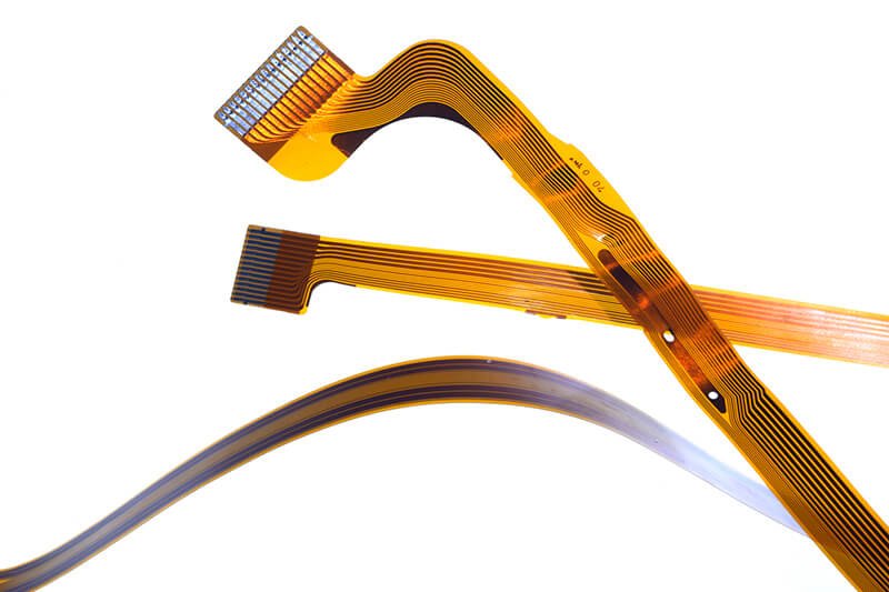

Design mistakes in flexible PCB projects can cause big problems. If you pick the wrong material or skip the right stack-up, you may pay more. You might also see more failures and hard manufacturing issues. Look at this table to see how your choices can change your project:
| Design Factor | Impact on Reliability | Impact on Manufacturability | Impact on Cost |
|---|---|---|---|
| Polyimide laminate | High | Good | High |
| Glass-epoxy laminate | Low | Easy | Low |
| Multi-layer | Medium | Complex | High |
| Thin laminate | Low | Difficult | Medium |
| Small plated holes | Low | Difficult | High |
Do you want to get better at flex PCB design? Try these tips and best ways to keep your flexible projects strong and safe:
- Good flex pcb design means less stress cracks and better strength.
- Picking the right bend radius and using curved traces helps your flexible pcb last longer.
- Working with your fabricator early makes your pcb easier to make and more dependable.
Key Takeaways
- Pick the correct bend radius and use curved traces. This helps stop cracks and makes your flex PCB last longer.
- Select tough materials like polyimide and rolled annealed copper. These materials help your PCB bend well and stay strong.
- Think about your stack-up and flex areas before you start. This helps you avoid trace damage and makes bending work better.
- Leave enough room between drilled holes and copper. This stops shorts and problems when making the PCB.
- Talk with your manufacturer early in the process. This helps you find issues, save money, and make a better flex PCB.
Bend Radius
Flexible PCB Bend Guidelines
When you design a flex circuit, you need to think about how much the flex board will bend. If you bend a flexible pcb too much, it can break or stop working. The IPC-2223 standard gives you clear rules for bend radius. For a single-layer flex board in a static application, you should use a minimum bend radius that is ten times the thickness of the flex. If your flex circuit will bend many times, you need a much bigger bend radius—one hundred times the thickness for single-layer, and even more for double-layer or multilayer flex boards.
Here’s a quick table to help you remember the minimum bend radius for flex circuits:
| PCB Type | Static Minimum Bend Radius Ratio | Dynamic Minimum Bend Radius Ratio |
|---|---|---|
| Single-layer | 10:1 | 100:1 |
Let’s say your flex board is 0.2 mm thick. For a static bend, you need at least a 2.0 mm bend radius. For a dynamic bend, you need 20.0 mm. If you use rolled annealed copper, your flex circuit will last longer in dynamic bends. You should also avoid putting vias or heavy parts in the bend area. Smooth transitions between rigid and flexible sections help your flex board stay strong.
Tip: Always use curved traces and keep them away from the bend line. This makes your flex circuit more reliable.
Consequences of Tight Bends
If you make the bend radius too small on your flex board, you risk big problems. Tight bends put a lot of stress on the copper and the flexible material. Your flex circuit can crack, delaminate, or even lose electrical connection. Sharp bends can thin out copper traces and cause them to break. You might see solder joints fail or vias crack, especially near high-stress areas.
- Tight bends can cause:
- Cracking and delamination in the flex board
- Broken copper traces in the flex circuit
- Electrical failures in your flexible pcb
- Weak solder joints and damaged vias
- Stress that moves away from the neutral bend axis, making thick traces more likely to break
You should always follow the minimum bend radius for your flex circuit. Use gradual curves instead of sharp angles. Place traces perpendicular to the bend line for better stability. Keep vias and pads away from bend areas. If you need to put them close, use teardrop shapes and keep them at least 20 mils away from the bend. Reinforce your flex board with stiffeners in high-stress zones.
If you ignore these guidelines, your flexible pcb may fail early. You will spend more time and money fixing problems. Good bend radius design keeps your flex board strong and your flex circuit working for a long time.
Trace Routing
Tapered Traces in Flex Circuits
When you work on flex circuit design, you want your traces to last through every bend. Straight, sharp-edged traces can crack or break when the flex board moves. Tapered traces help spread out the stress. You start with a wide trace at the pad and gently narrow it as it moves into the flex area. This shape lets the copper flex without snapping.
If you skip tapering, you might see cracks at the edge of the pad or where the trace meets a via. These spots get weak fast. Tapered traces also help with signal flow. They keep the current moving smoothly, which is important for high-speed flex circuits. You want to avoid sudden changes in width. Sudden changes can cause impedance mismatches and signal reflections.
Tip: Always use smooth, curved traces instead of sharp angles. Curves help your flex circuit handle stress better and keep your signals clean.
Avoiding Discontinuities
Discontinuities are breaks or sudden changes in your trace path. In flex pcb design, these can cause big problems. If you use 90° bends or let traces cross gaps in the reference plane, you risk signal loss and noise. Long return loops and poor grounding make things worse. Your flex board might pick up interference or lose data.
Here are some common mistakes in flex circuit design that you should avoid:
- Using traces that are too thin or too close together. This can cause overheating and short circuits. For example, a 1A current needs at least a 0.5 mm wide trace on 1 oz copper.
- Placing vias in bend areas. This puts stress on the via and can break the connection during flexing.
- Routing traces over gaps in the ground plane. This disrupts the return path and increases EMI.
- Using inconsistent trace widths. This leads to impedance mismatches and signal distortion.
- Not separating high-speed signals from sensitive ones. This increases crosstalk and noise.
If you want your flexible pcb to work well, keep your traces smooth and even. Plan your flex circuit layout so that traces run over solid ground planes. Place ground vias near signal vias to help return currents. Avoid too many vias and keep them away from bend zones. Good trace routing keeps your flex board strong and your signals clear.
Tear Stops and Stiffeners
Using Tear Stops
Tear stops play a big role in keeping your flex circuit safe from damage. When you bend or twist a flex circuit, stress can build up in certain spots. Tear stops help spread out this stress so your board does not rip or crack. You usually find tear stops at the ends of slots or cutouts in the flex. They act like little shields that stop a tear from moving further into the circuit.
Here’s why you want to use tear stops in your flex circuit:
- They reduce assembly errors by keeping the flex from bending too much during soldering.
- Tear stops help keep your flex circuit flat and lined up during production, which saves money.
- They protect solder joints from stress, especially when your flex circuit bends a lot.
- Tear stops make sure your flex circuit meets industry standards for strength and durability.
- They help your flex circuit last longer by stopping cracks before they start.
Tip: Place tear stops in areas where you see lots of flexing or where the flex circuit changes shape. This simple step can save you from big problems later.
Stiffeners in High-Stress Areas
Stiffeners give your flex circuit extra support where it needs it most. You add stiffeners to spots that hold heavy parts or connectors. These areas see a lot of bending and twisting, which can break solder joints or damage the flex. Stiffeners keep these zones rigid so your flex circuit stays strong.
You might use materials like polyimide, FR-4, or even metal for stiffeners. Each one gives a different level of strength and heat control. Here’s what stiffeners do for your flex circuit:
- They provide a flat, solid surface for placing and soldering parts.
- Stiffeners help your flex circuit handle heavy components without bending.
- They keep connectors stable, even if you plug and unplug them many times.
- Stiffeners help your flex circuit meet thickness rules for special connectors like ZIF.
- They make it easier to handle your flex circuit during assembly and testing.
If you skip stiffeners in high-stress areas, your flex circuit can fail early. You might see broken traces, loose connectors, or even total board failure. Always think about where your flex circuit will bend the most. Add stiffeners to those spots to keep your design safe and reliable.
Material Selection
Choosing Substrate and Copper
When you design flexible circuit boards, you must pick good materials. The materials you choose change how your board bends and how long it lasts. They also change how much your board costs. Polyimide is the most used substrate for flexible pcb designs. It is strong at high temperatures and bends without breaking. Polyester is cheaper and works for easy jobs, but it cannot take the heat from soldering. Liquid Crystal Polymer is another choice. It keeps out water and works well for high-frequency signals, but it costs more.
Take a look at this table to see the main flex circuit materials:
| Property | Polyimide (PI) | Polyester (PET) | Liquid Crystal Polymer (LCP) |
|---|---|---|---|
| Temperature Range | -200°C to 300°C | Low | High |
| Cost | Cost-effective | Low | Expensive |
| Dielectric Constant | ~2.4 – 3.48 | ~2.4 | ~2.85 |
| Moisture Resistance | Low | Low | High |
| Tensile Strength | High | High | High |
For copper, you can pick rolled annealed (RA) or electro-deposited (ED). RA copper is best for boards that bend a lot. It can stretch and bend without breaking. ED copper is okay for boards that do not bend much. You also need adhesives and coverlay films to keep your copper and substrate safe.
Tip: Always pick the right substrate and copper for your board’s job. If your flexible circuit boards will bend a lot, use polyimide and RA copper.
Rolled Annealed Copper for Flexibility
You want your flexible pcb to last through many bends. Rolled annealed copper helps with this. This copper has grains that go sideways, so it bends easily and does not crack. It has a smooth surface and is very strong. RA copper is best for flex circuits that move a lot, like in medical or aerospace devices.
Here is why RA copper is special:
- High ductility and flexibility
- Great at handling lots of bending
- Smooth surface for better signals
- Low spring back, so it keeps its shape
Electro-deposited copper has grains that go up and down. It feels rough and can break more when you bend it. ED copper costs less, but it is better for boards that do not flex much.
If you want your flexible circuit boards to last through lots of movement, RA copper is the best choice. It gives you better strength and signal quality, especially for high-frequency designs.
Stack-Up Design
Flex PCB Layer Stack-Up
When you start flex pcb design, you need to think about the stack-up. The stack-up is the order of layers in your flex circuit. You can pick from single-layer, two-layer, or even four-layer flex circuits. Some designs use rigid-flex, which mixes stiff and bendy parts. This setup lets you put parts on the rigid area while the flex part bends and moves.
Here’s what you usually find in a flex board stack-up:
- Polyimide (PI) for the flexible base
- Copper foil for the traces
- Adhesives to hold layers together
- Coverlay for protection
- FR4 for rigid sections in rigid-flex designs
A single-layer flex board often has a thin PI coverlay, adhesive, copper foil, and a PI base. The total thickness is about 83.5 microns. Rigid-flex boards use both FR4 and PI, so you get strength and flexibility in one pcb. This combo gives you better heat control, strong signal paths, and fewer places where things can break.
Tip: A good stack-up helps your flex circuit handle heat, bend without damage, and keep signals clean. It also saves space and weight, which is great for small gadgets.
Defining Flex Regions
You need to plan where your flex board will bend and where it will stay stiff. These are your flex regions. If you do not define these areas well, your flex circuit can fail fast. Twisting and bending put stress on the copper traces. If your stack-up is wrong, cracks can show up after just a few bends. You might see broken traces at the pad or where the trace meets a via.
Here’s what can go wrong with poor stack-up or flex region planning:
- Trace cracking and loss of connection
- Warping or delamination of the flex board
- Signal problems like noise or crosstalk
- Complete system failure
You should always keep high-stress areas free from vias and pads. Use the right materials and layer order for each flex region. Make sure your flex circuit design matches how the board will move in real life. This way, you get all the flex circuit design advantages—like better reliability, less weight, and easier assembly.
Note: Good flex pcb design means you get a flex circuit that lasts longer and works better. Always talk to your manufacturer about your stack-up and flex regions before you finish your design.
Drill-to-Copper Distance
Optimizing Drill Placement
When you design a flexible PCB, you need to think about where you put your drilled holes. Drill-to-copper distance means the space between the edge of a drilled hole and the nearest copper feature, like a trace or pad. If you get this wrong, you can run into big problems.
The best practice is to keep at least 10 mil (0.010 inch) between the edge of any hole and the closest copper. If you can, aim for 15 mil (0.015 inch) for even better results. This spacing helps you avoid electrical shorts and makes your board stronger. If you go below 7 mil, you make the board harder to build and more likely to fail.
Tip: Always check your design rules for drill-to-copper spacing before you send your files to the manufacturer. A little extra space can save you a lot of trouble later.
You can use a simple table to remember the safe distances:
| Drill-to-Copper Distance | Risk Level |
|---|---|
| 15 mil (0.015″) | Very Low |
| 10 mil (0.010″) | Acceptable |
| 7 mil (0.007″) or less | High Risk |
Preventing Damage
If you don’t leave enough space between your holes and copper, you can face many issues. Here are some of the most common problems:
- Electrical shorts can happen if copper gets too close to a hole.
- Holes that are too close to traces can cut into them, breaking the circuit.
- Not enough spacing can cause defects during manufacturing.
- Both plated and non-plated holes can cause trouble if they touch copper.
- Inner layers can short out if you skip proper clearance.
You want your flexible PCB to last and work well. Always keep enough distance between holes and copper. This simple step helps you avoid costly repairs and keeps your board safe during bending and assembly. If you follow these rules, you’ll have a much better chance of building a reliable flex circuit that stands up to real-world use.
IPC Standards
Flexible Printed Circuit Compliance
You want your flexible printed circuit to last and work well. That means you need to follow the right IPC standards. These rules help you design, build, and test your flexible printed circuit so it meets industry quality. IPC-6013 and IPC-2223 are the main standards for flexible printed circuit boards. IPC-6013 tells you how to check quality, test for strength, and make sure your board can handle bending and heat. IPC-2223 gives you design tips, like how to pick materials, where to put bends, and how to protect your board with coverlay.
Here’s a quick look at some important IPC standards and what they cover:
| IPC Standard | What It Covers | Why It Matters |
|---|---|---|
| IPC-6013 | Performance, testing, plating, and quality for flex PCBs | Makes sure your board works and lasts |
| IPC-2223 | Design rules for flex and rigid-flex PCBs | Helps you avoid design mistakes |
| IPC-6010 | General rules for all printed boards | Sets the base for quality |
| IPC-4203/4204 | Materials for coverlay and bonding | Keeps your layers safe and strong |
You should also know about IPC-A-600 for visual checks and IPC-TM-650 for testing things like peel strength and thermal shock.
Pre-Layout Considerations
Before you start your flexible printed circuit design, you need to plan for compliance. If you skip this step, you might run into problems later. Here are some common mistakes and how to avoid them:
- Use the right bend radius. For static flex, keep the bend radius at least 10 times the board thickness. For dynamic flex, use 20 times or more.
- Don’t put through-hole vias in bend areas. If you must, use special blind or buried vias and add extra support.
- Pick materials that bond well together. Poor choices can cause layers to peel apart when the board heats up or bends.
- Place stiffeners in the right spots. If you get this wrong, your board can crack or break.
- Make sure your coverlay covers all the flex areas. This keeps out moisture and stops solder from bridging.
- Plan smooth transitions between flex and rigid parts. Sudden changes can cause the board to fail.
Tip: Always check the latest IPC standards before you finish your design. Standards change, and you want your flexible printed circuit to pass every test.
If you follow these steps and work with your manufacturer, you can avoid most compliance problems. This helps your flexible printed circuit work better and last longer.
Manufacturing Constraints
Flex PCB Design for Manufacturability
When you begin a flex pcb design, think about how easy it is to make. Some designs look good on paper but are hard to build in the factory. You want your flex circuit to work well and not cost too much. Here are some things that can make building tricky:
- Special materials and tight rules make building harder and cost more.
- Layers can come apart or not line up right during lamination, especially in rigid-flex boards.
- Drilling and plating vias in flexible materials need special tools like lasers and careful control of plating thickness.
- Bends and places where the board changes can get stressed, which may cause copper to crack or peel.
- Complex stack-ups need careful lamination and the right glue.
- Testing is important. You need to check for bending, heat, and shaking to make sure your board lasts.
- Putting connectors or heavy parts in bend areas can make the board break early.
You can stop many problems if you talk to your manufacturer early. Share your design files, stack-up drawings, and bend area details. This helps them find problems before making your board. Always keep your bend radius big enough to stop cracks. Try not to put vias or lots of traces in bend zones. If you plan ahead, your flex pcb will be easier to build and last longer.
Tip: Ask your manufacturer what materials and steps they like best. This can help you save time and money.
Choosing the Right Manufacturer
Picking the right manufacturer is very important for your project. Not every company can make every flex circuit design. You want someone with the right skills and tools. Here’s what to look for:
- Certifications like ISO 9001 or UL show they care about quality.
- Check if they can make the size, shape, and number of layers you need.
- See if they offer special things like blind or buried vias.
- Ask about their experience with flex pcb design and tough builds.
- Good customer service and clear answers help your project go well.
- Compare prices and how fast they work, but the cheapest is not always best.
- Some manufacturers help you make your design better and cheaper.
Material choices, copper thickness, and trace spacing all change price and how well your board works. A skilled manufacturer can help you pick the best options. If you work together from the start, you can avoid expensive changes later. Your flex circuit will be stronger, more reliable, and ready for real use.
Collaboration
Early Communication with Fabricators
You want your flexible printed circuit to work well. To do this, talk to your fabricator early in the design. Working together from the start helps you find problems before they cost a lot. Here are some things you get by talking early:
- You get advice about materials and what the factory can make.
- Fabricators check your design files and find mistakes you may not see.
- You can make a prototype to test how your board bends and works.
- Prototyping lets you fix problems without wasting time or parts.
- Teamwork helps your design fit what the factory does best, like trace width or layers.
- You can make your design simpler, which saves money and helps more boards pass.
If you plan ahead and ask questions, you avoid last-minute problems. Your design will work in real life, and you get a better board.
Sharing Flex PCB Design Requirements
Talking clearly with your fabricator keeps your project going well. If you share all your design needs, you lower the chance of mistakes when making your board. Here is how sharing details helps:
- You stop weak bonding by making sure glue is used right.
- You avoid warping or cracking by picking materials that bend the same way.
- You stop trace cracks by putting stiffeners in the right places.
- Using good, matching materials keeps your board strong and bendy.
- Good notes and clear build steps help the factory know your design.
- You can show which parts are most important, like trace width or via size, so everyone checks them.
Using online tools lets you and your fabricator see changes right away. This way, everyone uses the newest design. You also stop mix-ups by sharing stack-up and material lists. When you agree on every step, you get a flexible printed circuit that works well and does not get delayed.
Cost Factors
Design Choices and Expenses
When you design flex circuits, your choices change the price a lot. Some choices make your project cost more, but others help you save money. Here are the main things that make costs go up:
- If you pick high-quality materials like special laminates or thick copper, your board gets stronger but costs more.
- Making bigger flex circuits uses more material and takes more time to build.
- Adding more layers makes the price go up by about 10-20% for each extra layer.
- Fancy finishes, like ENIG or immersion gold, make the board last longer but also cost more.
- Thicker boards or custom shapes mean you pay more for both materials and time.
- Special features, like buried vias or stiffeners, make the price higher.
You can see how these choices change your budget in the table below:
| Design Factor | Cost Impact |
|---|---|
| High-quality materials | 20-30% higher than standard options |
| More layers (e.g., 6 vs. 2) | 50-70% higher |
| Complex features (blind/buried vias) | Up to 200% higher |
| Common design mistakes | 10-15% extra for fixes and rework |
| Early manufacturer collaboration | Saves 10-15% on redesigns |
| Semi-flex instead of full flex | 20-40% savings |

Strategies for Cost-Effective Flex Circuits
You can keep your flex circuits cheap and still make them work well. Try these smart ideas:
- Use fewer layers if you can. Simple designs cost less and are easier to build.
- Pick regular materials like normal polyimide or PET for parts that do not need to be special.
- Do not use too many vias, especially blind or buried ones. Use standard through-hole vias instead.
- Place parts and traces in smart spots to use the board space well. This helps you make smaller boards and save on materials.
- Follow design for manufacturability (DFM) rules. Give enough space between traces and do not use tight bends.
- Use regular parts instead of custom ones. This helps you get parts faster and pay less.
- Work with your manufacturer early. They can help you find ways to save money and avoid mistakes.
- Order more boards at once to get a better price.
If you plan ahead and keep your design simple, you can make flex circuits that work well and do not cost too much.
Testing and Prototyping

Validating Flexible PCB Designs
You want your flexible PCB to work right the first time. Testing and prototyping help you catch problems before you build a lot of boards. Here are steps you should follow to validate your design:
- Keep your bend radius at least ten times the thickness of your flex stack. This stops conductor fatigue.
- Calculate trace width and spacing based on how much current you need and the copper thickness. This helps you avoid shorts when the board bends.
- Place parts away from bend areas. Use stress-relief pad shapes near holes and bends.
- Pick coverlay materials that protect traces but still let your board bend.
- Design for heat control. Use thermal vias, copper planes, or stiffeners where needed.
- Simulate controlled impedance for high-speed signals. Add ground planes or shielding to cut down on EMI.
- Learn the steps your manufacturer uses, like copper cladding, etching, drilling, and electrical testing. This helps you make sure your prototype matches the final product.
- Know that prototypes and mass production are different. Prototypes let you test and change things before you make a big batch.
Tip: Always build engineering validation test samples with the same stack-up and materials you plan to use in production. Test these samples for function, electrical performance, and how they handle heat and bending.
Common Testing Mistakes
You can avoid many problems if you know what mistakes to watch for during testing. Here are some common errors people make:
- Using rigid PCB rules for flexible sections. Flexible PCBs need smooth transitions and no sharp corners.
- Picking the wrong via pad sizes. Always match pad sizes to drill sizes and check with your fabricator.
- Placing plated holes too close to rigid-flex transitions. Keep a safe distance to lower stress.
- Adding too much copper on flexible layers. Use cross-hatched patterns instead of solid fills.
- Using solid copper in bend areas. This can cause delamination. Cross-hatched copper works better.
- Using the wrong amount of adhesive in the stack-up. Work with your fabricator to get it right.
- Not defining bend radius. Always write down the bend radius in your design notes.
- Routing traces with sharp angles in bend regions. Curved traces last longer.
- Putting vias in high-stress bend areas. Avoid this or reinforce them.
- Leaving unsupported SMT pads. Use anchoring spurs and pad fillets to keep pads in place.
Note: Careful testing and prototyping save you time and money. You get a flexible PCB that works well and lasts longer.
You can stop most problems in flex circuits by using smart design steps. Make sure you use the right bend radius and choose strong materials. Plan your stackup so your board bends well and lasts longer. Work with skilled manufacturers and use a checklist to find mistakes early.
- Try design tips like keeping enough space between traces and using solid ground planes. This helps your signals stay clear.
- Test your flex circuits before making a lot of them. This helps you find problems early.
Always remember, each project teaches you something new. This helps you make better and stronger flex circuits next time.
FAQ
What is the best material for flexible PCBs?
Polyimide works best for most flex circuits. You get strong heat resistance and good flexibility. If you need something cheaper, polyester is an option, but it cannot handle high temperatures.
How do I stop my flex PCB from cracking?
You should use a large bend radius and curved traces. Keep vias and pads away from bend areas. Add stiffeners in high-stress zones. Always follow IPC guidelines for bend radius.
Can I use regular PCB design rules for flex circuits?
No, you need special rules for flex PCBs. Use smooth curves, avoid sharp corners, and pick materials that bend well. Regular PCB rules can cause cracks and early failures.
Why do manufacturers ask for detailed stack-up drawings?
Stack-up drawings help your manufacturer understand your layer order and materials. You avoid mistakes and get a board that matches your needs. Clear drawings save time and money.
How do I test my flexible PCB before mass production?
Build a prototype with the same materials and stack-up. Bend and twist it to check for cracks. Test electrical performance and heat resistance. Fix any problems before you order a big batch.
